
Vapor Chamber Cooling: The Engineer's Design Guide
- Jewlz Technologies

- Aug 16
- 17 min read
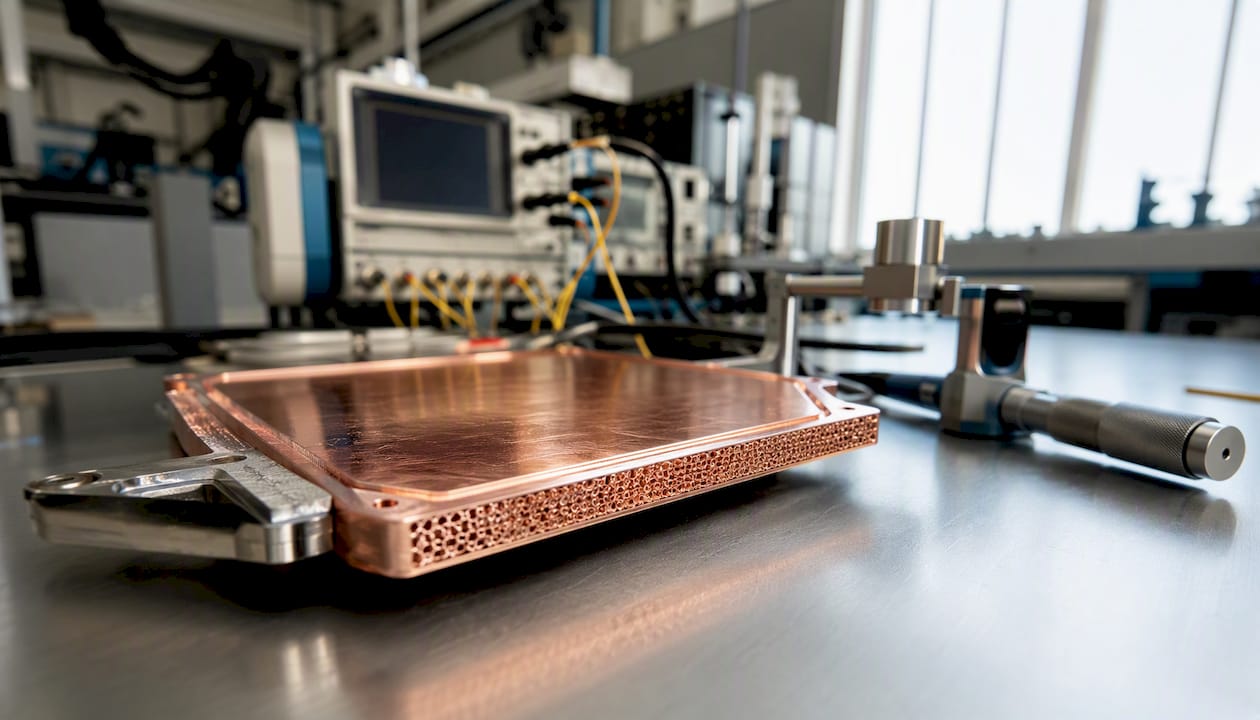
A vapor chamber is a flat, sealed two-phase heat spreader that uses evaporation, vapor transport, and capillary-driven condensate return to move heat across a plane with very low spreading resistance. Choose it when you have a small, high-power hotspot that must be spread to a larger heat sink footprint, your thickness budget is constrained, and a heat pipe array would leave unacceptable temperature gradients. When convection coefficients are high enough for a liquid cold plate to dominate, solid copper or microchannels often win on cost and simplicity.
Quick selection guide:
High localized heat flux, air-cooled system: A vapor chamber typically outperforms a copper spreader once the hotspot heat flux climbs above what conduction alone can spread without an unacceptable junction temperature rise.
Thin form factor with multi-hotspot die: Vapor chambers distribute heat across the entire footprint simultaneously, unlike a heat pipe array that creates discrete transport paths.
Mobile or consumer electronics with tight z-height: Sub-millimeter vapor chambers are now production-viable, though vapor-core resistance rises sharply below 1 mm thickness.
Caveat: Vapor chambers are orientation-sensitive. Performance can degrade when the device tilts more than roughly 15° from horizontal because capillary return weakens, raising dry-out risk. Confirm orientation tolerance with your supplier before committing to a design.
Key Takeaways
Vapor chamber cooling outperforms solid copper spreaders when hotspot heat flux is high, the footprint-to-hotspot area ratio exceeds 5:1, and the system is air-cooled — but wick selection, fill volume control, and interface management determine whether the device delivers its rated performance.
Point | Details |
When to choose a vapor chamber | Use when hotspot heat flux exceeds ~50 W/cm² and the footprint-to-hotspot area ratio is 5:1 or greater in an air-cooled system. |
Wick selection drives CHF | Optimize wick permeability and pore size together; maximizing capillary pressure alone raises liquid pressure drop and can lower CHF margin. |
Thin devices need special attention | Below 1 mm thickness, vapor-core resistance dominates; verify this in your CTM before finalizing vapor gap height. |
CTM before hardware | A validated compact thermal model runs 214× faster than CFD and is accurate enough for early-stage design selection and parameter sweeps. |
Jewlztech Thermalysis Toolkit | Supports CTM-based parameter sweeps with built-in material databases — use it to define wick specifications before writing your RFQ. |
Table of Contents
How does vapor chamber cooling work?
The operating cycle has four stages. Understanding each one tells you where your thermal resistance budget actually goes.
Evaporator zone: Heat enters through the envelope wall into the wick structure. In the thin liquid film at the wick-vapor interface, evaporation occurs at very low superheat, which is the dominant heat-transfer mechanism at moderate heat flux. At higher flux, nucleate boiling can initiate within the wick pores. Both mechanisms drive vapor generation.
Vapor transport: Vapor travels across the internal cavity at near-saturation conditions. Because the latent heat of water is high (roughly 2,260 kJ/kg at 100°C), even a small mass flow rate carries substantial power. The vapor-core pressure drop is usually small compared to the liquid-side pressure drop, but it becomes the limiting resistance in sub-millimeter devices where the vapor gap is thin.
Condenser zone: Vapor reaches the cooler regions of the envelope, condenses on the wick surface, and releases its latent heat to the heat sink or cold plate above.
Capillary return: The wick’s capillary pressure drives condensate back to the evaporator. This is the engine of the whole system, and it sets the hard performance ceiling.
The capillary pressure budget governs everything:
$$\Delta P_{cap} \geq \Delta P_{liquid} + \Delta P_{vapor} + \Delta P_{gravity}$$
When liquid-side pressure drop through the wick exceeds available capillary pressure, the evaporator wick dries out. That condition, the capillary limit, defines the maximum heat transport capacity (critical heat flux, or CHF) for a given wick geometry and working fluid. Thermal resistance and HTC are the metrics you optimize; CHF is the hard wall you must not hit.
Dominant resistances at a glance:
Wick thermal resistance: Dominates at moderate heat flux; reduced by using high-conductivity sintered copper wicks or thin wick layers.
Vapor-core saturation gradient: Usually negligible in devices thicker than 2 mm; becomes the primary resistance in ultra-thin designs.
Envelope conduction: Typically minor for copper envelopes but relevant for silicon or polymer designs.
Interface resistances (TIM, solder): Often larger than the vapor chamber’s own resistance — a common design oversight.
Statistic: A compact thermal model for micropillar-wick vapor chambers achieved a maximum error of 1.25°C versus full CFD while running 214× faster, which means early-stage design sweeps that would take days in CFD can run in minutes.
Internal components and wick types
The envelope, wick, and working fluid are the three material decisions that determine whether your vapor chamber hits its thermal targets or fails at the capillary limit.
Envelope materials and working fluids
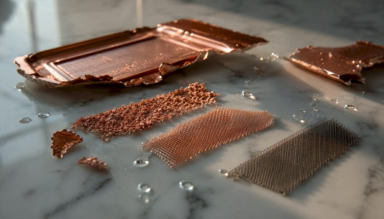
Copper is the dominant envelope material for electronics cooling because it pairs well with water, offers high thermal conductivity (~385 W/m·K), and is compatible with standard brazing and diffusion-bonding processes. Aluminum is lighter and cheaper but requires a compatible working fluid (ammonia or acetone) because water corrodes aluminum. Silicon envelopes enable CTE-matched integration directly to silicon dies and allow finer wick geometry control through MEMS fabrication, but wafer-level manufacturing and mechanical reliability remain open challenges. For high-temperature power electronics above 150°C, water is replaced by higher-boiling-point fluids such as Dowtherm A or biphenyl.
Wick type comparison
Wick type | Capillary pressure | Permeability | Effective thermal conductivity | Manufacturability |
Sintered powder | High (small pores, ~1–50 µm) | Low | High (copper matrix, ~10–40 W/m·K) | Mature; batch sintering in copper envelopes |
Screen/mesh | Moderate | Moderate | Moderate (~5–15 W/m·K) | Simple; easy to cut and layer |
Axial grooves | Low–moderate | High | Low (vapor fills grooves) | Machined or extruded; low cost |
Micropillar arrays | High (tunable geometry) | Moderate–high | Moderate | Photolithography; silicon or electroplated copper |
Biporous/hierarchical | Very high | High | Moderate–high | Complex; sintered with pore-former or dual-scale etching |
Sintered powder:
High capillary pressure supports high CHF.
Thermal conductivity is good but wick thickness must be controlled tightly.
Difficult to achieve uniform density across large footprints.
Screen/mesh:
Easy to prototype and stack for variable wick thickness.
Lower capillary pressure than sintered powder limits peak heat flux.
Prone to mesh deformation under high clamping loads.
Grooves:
Excellent permeability means low liquid pressure drop at moderate heat flux.
Capillary pressure is low, so CHF is limited; grooves flood easily if tilted.
Lowest manufacturing cost for simple geometries.
Micropillar arrays:
Micropillar wicks can increase capillary pumping and extend the dry-out heat flux compared with conventional wicks at the same thickness.
Geometry is precisely tunable (pillar diameter, pitch, height) for a specific fluid and power target.
Requires photolithography or electroplating, which adds cost and limits to silicon or electroplated copper substrates.
Biporous/hierarchical:
Combines large pores (high permeability) with small pores (high capillary pressure) in a single wick layer.
Highest theoretical CHF among passive wick structures.
Manufacturing complexity is significant; yield and repeatability are active research areas.
A key insight from the literature: maximizing capillary pressure alone can backfire. Reducing pore size raises capillary pressure but simultaneously reduces permeability, increasing liquid-side pressure drop and potentially lowering the CHF margin rather than raising it. The right wick optimizes both simultaneously.
Key design variables every engineer must size
Getting a vapor chamber right means controlling six variables before you ever talk to a supplier.
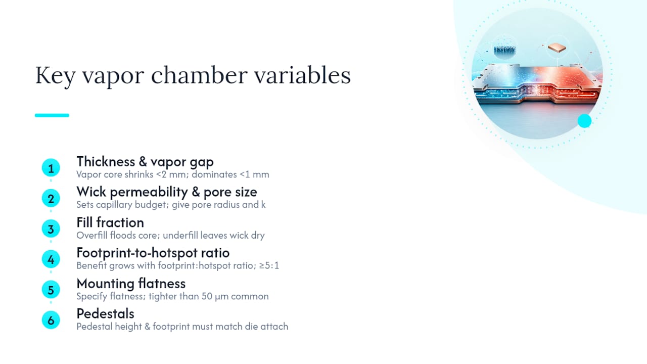
Thickness and vapor gap: Total device thickness is split between two envelope walls, two wick layers, and the vapor core. In devices thinner than 2 mm, the vapor core height drops fast, and vapor pressure drop rises. Below 1 mm, vapor-core resistance often dominates the entire device thermal resistance. The optimal wick thickness balances wick thermal resistance against flow pressure drop — thinner wicks reduce conduction resistance but also reduce permeability cross-section, raising liquid pressure drop.
Wick permeability and pore size: These two parameters set the capillary pressure budget and the liquid pressure drop. They cannot be optimized independently. Specify both effective pore radius and permeability when writing an RFQ.
Fill fraction: Overfilling floods the vapor core and raises vapor-core resistance. Underfilling leaves the wick partially dry at startup.
Footprint and hotspot area ratio: The spreading benefit of a vapor chamber grows as the ratio of total footprint to hotspot area increases. A 5:1 ratio or greater is where the performance gap over solid copper becomes substantial.
Mounting flatness: Flatness directly affects TIM thickness and contact resistance. Specify flatness tolerance in your RFQ; values tighter than 50 µm across the die contact area are common for server-class applications.
Pedestals: Raised copper pedestals on the evaporator side reduce the distance between the die and the active wick, cutting conduction resistance through the envelope wall. Pedestal height and footprint must match the die attach area precisely.
Example sizing outline
Follow this sequence when you start a new design:
State the boundary conditions: Heat input Q (W), hotspot area (mm²), maximum allowed junction-to-ambient thermal resistance (°C/W), and system orientation.
Estimate required spreading resistance: Subtract the estimated convection resistance (fin + TIM) from the total budget. The remainder is your vapor chamber allowance.
Select working fluid and envelope material: Water/copper for 40–120°C operating range; adjust for temperature extremes.
Choose wick type based on heat flux: If hotspot heat flux exceeds roughly 100 W/cm², sintered powder or micropillar wicks are the starting point. Below that, grooves or mesh may suffice.
Size vapor core height: Start with 0.3–0.5 mm for thin designs; verify vapor pressure drop is below 10% of capillary pressure budget.
Calculate capillary pressure budget vs. pressure losses: Check that ΔP_cap ≥ ΔP_liquid + ΔP_vapor + ΔP_gravity at worst-case orientation.
Verify CHF margin: Target at least 1.5× safety factor on CHF relative to your maximum operating heat flux.
Specify fill volume: Calculate optimal charge from wick void volume and thermal expansion of the fluid; add ±5% tolerance to the RFQ.
What are the thermal performance limits of a vapor chamber?
Defining the key metrics
Thermal resistance (R_th): The ratio of temperature difference (evaporator surface to condenser surface) to heat input, in °C/W. For a well-designed copper/water vapor chamber at moderate heat flux, total device thermal resistance typically falls in the range of 0.01–0.1 °C/W depending on footprint and power level.
Effective thermal conductivity (k_eff): An equivalent in-plane conductivity used in system-level models. Values of 10,000–50,000 W/m·K are commonly cited for copper/water devices, though this figure is geometry- and power-dependent and should not be used as a fixed material property in a thermal model.
Heat transfer coefficient (HTC) at the evaporator: Governs how efficiently heat moves from the wick into the vapor. Thin-film evaporation in micropillar wicks produces very high local HTCs, which is why micropillar designs push CHF higher than groove wicks at the same thickness.
Critical heat flux (CHF) and dry-out: CHF is the heat flux at which the capillary limit is reached and the evaporator wick begins to dry out. The wick capillary characteristics — effective pore size and permeability — are the primary determinants of CHF. Dry-out causes a sudden, large rise in evaporator temperature and can permanently damage the wick structure.
Practical limits and failure modes
Dry-out: Capillary limit exceeded; evaporator temperature spikes. Mitigate by increasing wick capillary pressure, reducing liquid path length, or derate the operating power.
Wick flooding: Condenser-side wick becomes oversaturated, blocking vapor flow. Usually caused by overfilling or insufficient vapor core height.
Noncondensable gas (NCG) accumulation: Residual air or dissolved gases collect in the vapor core, blocking condensation and raising thermal resistance over time. Mitigate through thorough evacuation and degassing during manufacturing.
Envelope deformation: Differential pressure between internal vapor and ambient can cause bulging, especially in thin aluminum envelopes. Some devices have documented power limits around 500 W; exceeding them risks permanent deformation.
Orientation sensitivity: Performance degrades when tilted more than roughly 15° from horizontal because gravity adds to the liquid pressure drop, reducing the capillary margin.
Statistic: Numerical studies on ultra-thin vapor chambers show that vapor-core thermal resistance becomes significant below approximately 1 mm thickness, which means the common assumption of negligible vapor-core resistance breaks down precisely in the form factors most popular in mobile devices.
Measurement setup
A standard test rig uses a calibrated heater block (resistive cartridge heater) pressed against the evaporator surface with a known contact pressure and TIM. Thermocouples or RTDs are embedded at four to six locations: two on the evaporator surface, two on the condenser surface, and at least one on the heat sink base. Heat flux is calculated from heater power divided by heater contact area. Thermal resistance is computed from the evaporator-to-condenser temperature difference divided by total power. Validate at three to five power levels bracketing the expected operating range.
How vapor chambers are manufactured and charged
Manufacturing a vapor chamber is as much a process-control problem as a design problem. A geometrically perfect wick with a poor evacuation procedure will fail within months.
Step-by-step manufacturing outline:
Substrate preparation: Machine or stamp copper (or etch silicon) envelope halves to final geometry, including pedestal features and wick support pillars.
Wick assembly: Sinter powder wick inside the lower envelope half (for sintered designs) or bond a pre-formed mesh/micropillar layer. Wick uniformity across the footprint is critical — inspect with cross-section microscopy on sample coupons.
Bonding: Join upper and lower envelope halves by diffusion bonding, brazing, or (for silicon) anodic bonding. Seal quality determines long-term leak rate.
Evacuation of noncondensables: Pull vacuum through a fill port to below 10⁻³ Torr, typically with a turbomolecular pump. Bake the assembly at 80–120°C during evacuation to drive off adsorbed gases from wick surfaces.
Degassed fluid charging: Introduce a precisely measured volume of degassed working fluid through the fill port. Fill volume is calculated from wick void volume and target fill fraction; precise evacuation and fill volume control are critical, and wafer-scale filling remains a challenge for silicon vapor chambers.
Port sealing: Cold-weld or solder-seal the fill port. Leak check with a helium mass spectrometer to verify seal integrity.
Final inspection: Flatness measurement (profilometer), burst pressure test, and thermal performance spot-check on a sample from each production batch.
Material trade-offs
Copper envelopes dominate production because the water/copper system is well-characterized, compatible with standard brazing, and offers high thermal conductivity. Aluminum is lighter but requires ammonia or acetone as the working fluid, which complicates handling and sealing. Silicon envelopes allow CTE-matched attachment directly to silicon dies and enable MEMS-fabricated micropillar wicks with sub-10-µm feature sizes, but they are brittle and currently limited to individual-device manufacturing rather than wafer-scale volume production.
Pro Tip: Request a certificate of conformance that includes measured fill volume (in µL), final vacuum level (in Torr) before sealing, and flatness measurement (in µm) for every production lot. These three numbers tell you more about long-term reliability than any marketing specification.
How to integrate a vapor chamber into your system
A vapor chamber’s thermal resistance is only part of the story. Interface resistance between the vapor chamber and the die, and between the vapor chamber and the heat sink, often exceeds the device’s own resistance. Getting integration right is where most of the performance is won or lost.
Integration patterns
Soldered fin stack: Fins are brazed or soldered directly to the condenser surface of the vapor chamber. This eliminates the fin-base interface resistance and is the preferred approach for high-performance air-cooled designs. Solder joint quality and flatness of the condenser surface are critical.
Pressure-mounted pedestal to die: A raised copper pedestal on the evaporator side contacts the die through a thin TIM layer, held in place by a bolted retention frame. This is the standard approach in server CPUs and GPUs.
Hybrid with heat pipes or liquid cold plates: Vapor chambers can be paired with heat pipes to extend heat transport over longer distances, or used as a spreading layer beneath a liquid cold plate. In the latter case, the performance advantage over solid copper narrows at high convection coefficients, and the cost premium may not be justified.
Practical assembly guidance
TIM thickness: Target the thinnest bondline your surface flatness allows. For indium foil or phase-change materials, 50–100 µm is typical at the die interface. Thicker TIM layers add 0.05–0.2 °C/W per 100 µm depending on TIM conductivity.
Clamping pressure: Vendor guidance recommends contact pressures up to 90 psi for some interfaces to maximize thermal contact. Verify that the vapor chamber envelope can withstand the specified clamping load without deformation.
Pedestal clearance: Pedestal height must account for TIM compression and PCB bow. A pedestal that is too tall creates a gap; one that is too short over-compresses the TIM and risks die cracking.
Fin attachment: For soldered fin stacks, refer to pin fin heat sink attachment practices for solder joint design and thermal cycling reliability guidance.
Pro Tip: Before committing to a TIM material, measure the actual surface flatness of both the vapor chamber pedestal and the die lid with a profilometer. A 100-µm bow across a 40 mm pedestal can double your effective TIM bondline thickness and add 0.1–0.3 °C/W to your interface resistance — more than the vapor chamber itself contributes.
Common assembly mistakes:
Over-torquing mounting screws, which bows the vapor chamber and creates uneven TIM contact.
Using a TIM with insufficient wetting on copper pedestals, leaving air pockets at the interface.
Failing to account for differential thermal expansion between the vapor chamber and the PCB during thermal cycling, which can crack solder joints on soldered fin stacks.
Vapor chambers vs. heat pipes and other cooling approaches
The right choice depends on your hotspot geometry, power density, available thickness, and system complexity budget. For a broader decision framework between passive and active systems, the active vs. passive cooling decision guide covers the full trade-off space.
Scenario | Recommended approach | Rationale |
Single small hotspot, air-cooled, >50 W/cm² | Vapor chamber | Low spreading resistance across full footprint |
Multiple discrete hotspots, linear layout | Heat pipe array | Pipes route to each hotspot independently |
Very high total power (>500 W), liquid available | Microchannel liquid cold plate | Higher total capacity; pumping power acceptable |
Thin mobile device, <3 mm z-height | Vapor chamber (sub-mm) | Best in-plane spreading at constrained thickness |
High-power wide-bandgap device, >200 W/cm² | Hybrid VC + liquid cold plate | VC spreads hotspot; liquid removes total power |
Cost-sensitive, moderate heat flux | Solid copper spreader | Simpler, cheaper, adequate at lower flux |
Heat pipe arrays:
Lower cost per unit than vapor chambers.
Excellent for routing heat over long distances.
Poor at spreading across a 2D footprint; temperature gradients between pipes are unavoidable.
Preferred when hotspots are discrete and linearly arranged.
Microchannel liquid cooling:
Highest heat flux capability of any passive or active approach.
Requires a pump, reservoir, and leak-tight plumbing, which adds system complexity and failure modes.
Operating cost includes pumping power; maintenance includes filter replacement and fluid management.
See the thermal management comparison for high-power applications for a detailed side-by-side.
Solid copper spreader:
Zero failure modes, lowest cost, easiest to integrate.
Loses to vapor chambers once hotspot heat flux is high enough that conduction spreading resistance dominates the thermal budget.
Selection rule of thumb: If your hotspot-to-spreader area ratio exceeds 5:1 and your hotspot heat flux is above roughly 50 W/cm², a vapor chamber almost always outperforms solid copper in an air-cooled system. Below that threshold, run the numbers on copper first before adding the cost and complexity of a two-phase device.
Vapor chamber design checklist and RFQ fields
Use this list at design review and when writing a supplier RFQ. Nothing here is optional.
Design checklist
Confirm hotspot area, total power, and maximum junction-to-spreader temperature rise.
Verify orientation in the final system and confirm capillary margin at worst-case tilt angle.
Select working fluid and envelope material compatible with operating temperature range.
Choose wick type based on hotspot heat flux and CHF target; confirm wick permeability and pore size are co-optimized.
Size vapor core height; verify vapor pressure drop is below 10% of capillary pressure budget.
Calculate fill volume and specify ±5% tolerance on the RFQ.
Specify flatness tolerance at the die contact area (typically ≤50 µm for server-class applications).
Confirm pedestal height, footprint, and material match die attach geometry.
Define acceptance test: thermal resistance at stated heat flux, CHF or derating curve, and leak rate.
Request sample cross-section microscopy data to verify wick uniformity on production lots.
RFQ fields to require from suppliers
Measured fill volume per unit (µL) and tolerance.
Final vacuum level before sealing (Torr).
Flatness measurement at evaporator surface (µm).
Thermal resistance at two or three specified heat flux levels (°C/W).
Burst pressure test result (psi or bar).
NCG measurement method and acceptance limit.
Shelf life and storage conditions.
Quick rules of thumb for early-stage trade studies:
If your design is still parametric (hotspot size or power not yet fixed), simulate with a compact thermal model before ordering hardware. A CTM sweep across wick geometry and fill fraction takes hours; a prototype takes weeks.
If your design is fixed and within 20% of a supplier’s standard catalog size, order a standard part first and test it. Custom tooling adds 8–16 weeks and significant cost.
If your hotspot heat flux exceeds 150 W/cm², treat CHF as the primary design constraint and work backward to wick geometry — do not start with a catalog part.
Modeling and simulation workflow for vapor chamber design
CFD vs. compact thermal models
Full CFD of a vapor chamber resolves the two-phase flow field, wick transport, and vapor dynamics simultaneously. It is the highest-fidelity approach and the right tool for final design validation or for studying a novel wick geometry. The cost is high: a single CFD run for a realistic device can take hours to days, and parametric sweeps across wick geometry, fill fraction, and hotspot location are computationally prohibitive in early design stages.
Compact thermal models (CTMs) replace the detailed two-phase physics with a network of thermal resistances and a saturation-temperature node representing the vapor core. They run in seconds to minutes and are accurate enough for design selection and parameter sweeps. The 214× speedup of a validated CTM versus CFD means you can sweep dozens of design points in the time a single CFD run takes.
For simulation tool options beyond full CFD packages, the Ansys alternatives overview covers several tools relevant to thermal modeling workflows.
CTM workflow: step by step
Define the resistance network: Model the vapor chamber as a 2D grid of cells, each containing a wick thermal resistance (evaporator side), a vapor-core node at saturation temperature, and a condenser-side wick resistance. Couple adjacent cells through lateral vapor transport.
Parameterize wick properties: Input effective thermal conductivity, permeability, and pore radius for the chosen wick type. These are the primary sweep variables.
Set boundary conditions: Apply heat flux at the hotspot cell(s) and convection boundary at the condenser surface. Include TIM and interface resistances.
Run parameter sweep: Vary wick thickness, vapor core height, and fill fraction across the feasible range. Track thermal resistance and CHF margin at each point.
Identify the Pareto front: Find the combinations that minimize thermal resistance while maintaining CHF margin ≥ 1.5×.
Validate against test data: Build one or two hardware samples at the predicted optimum. Measure thermal resistance at three to five power levels and compare against CTM predictions. Adjust wick effective conductivity or permeability if measured resistance deviates by more than 10%.
Validation metrics and measurement setup
Validation metric | Measurement method | Acceptable deviation |
Evaporator thermal resistance | Thermocouple array, calibrated heater | ≤10% vs. CTM prediction |
Condenser surface temperature uniformity | IR camera or thermocouple grid | ≤5°C variation across footprint |
CHF / dry-out onset | Step-power test to failure | Within 15% of predicted CHF |
Vapor-core resistance (thin devices) | Two-thermocouple method, evap vs. cond | ≤15% vs. model at sub-1 mm thickness |
Pro Tip: Run your CTM sweep first with wick thermal conductivity and permeability as free variables, then use the optimal values to specify wick geometry to your supplier. This inverts the usual workflow — instead of accepting whatever wick a supplier offers and hoping it works, you arrive at the RFQ knowing exactly what wick properties you need.
Jewlztech’s Thermalysis Toolkit supports exactly this kind of parameter sweep workflow, with built-in property databases for common wick materials and working fluids, making it a practical starting point for CTM-based vapor chamber sizing before committing to hardware.
Why vapor chambers deserve more engineering attention than they get
The thermal management community has spent the last decade chasing liquid cooling as the default answer to rising chip power densities. That instinct is understandable — microchannels and cold plates scale well and the physics are straightforward. But the framing misses something: the problem in most modern electronics is not total power removal, it is hotspot spreading. A 300 W chip with a 5 mm² hotspot does not need more coolant flow. It needs a spreader that can move heat laterally fast enough to prevent the junction from seeing 200°C while the rest of the package sits at 80°C.
Vapor chambers solve exactly that problem, and they do it passively, with no pump, no plumbing, and no moving parts. The reliability argument for passive two-phase spreading is stronger than it looks on paper. The failure modes are real — dry-out, NCG accumulation, envelope deformation — but they are all manageable with proper design and manufacturing controls. A well-specified copper/water vapor chamber with a sintered wick, properly evacuated and sealed, has a service life measured in years under normal operating conditions.
What I find underappreciated is the modeling gap. Most engineers either skip the CTM step entirely (and order a catalog part that may or may not work) or jump straight to full CFD (and spend weeks on a design that could have been evaluated in hours). The compact thermal model workflow is the middle path that the literature validates clearly, and it is the one that actually accelerates hardware development. Jewlztech’s Thermalysis Toolkit is built around exactly this kind of physics-based parameter sweep, which is why I point engineers there when they are starting a new vapor chamber sizing exercise.
Thermalysis Toolkit: faster vapor chamber sizing for working engineers
Sizing a vapor chamber from first principles takes time — not because the physics are opaque, but because the parameter space is large. Wick geometry, fill fraction, vapor core height, and hotspot location all interact, and evaluating them one at a time in a spreadsheet or a full CFD package is slow.

The Thermalysis Toolkit from Jewlztech is built for exactly this stage of the design process. It supports CTM-based thermal parameter sweeps across wick properties, fill fractions, and boundary conditions, with a built-in material property database covering common wick materials and working fluids. Output is documentation-ready, so the results from a design sweep go directly into a design review or RFQ without reformatting. Engineers working on vapor chamber sizing, conduction spreading analysis, or system-level thermal budgets can run the Thermalysis Toolkit as a downloadable Excel-based tool. Start a free trial or explore the toolkit at Jewlztech to see how quickly a CTM sweep narrows your design space before you commit to hardware.
Sources
Recommended
Comments