
How a Heat Pipe Actually Moves Heat, Step by Step
- Jewlz Technologies

- 2 days ago
- 17 min read
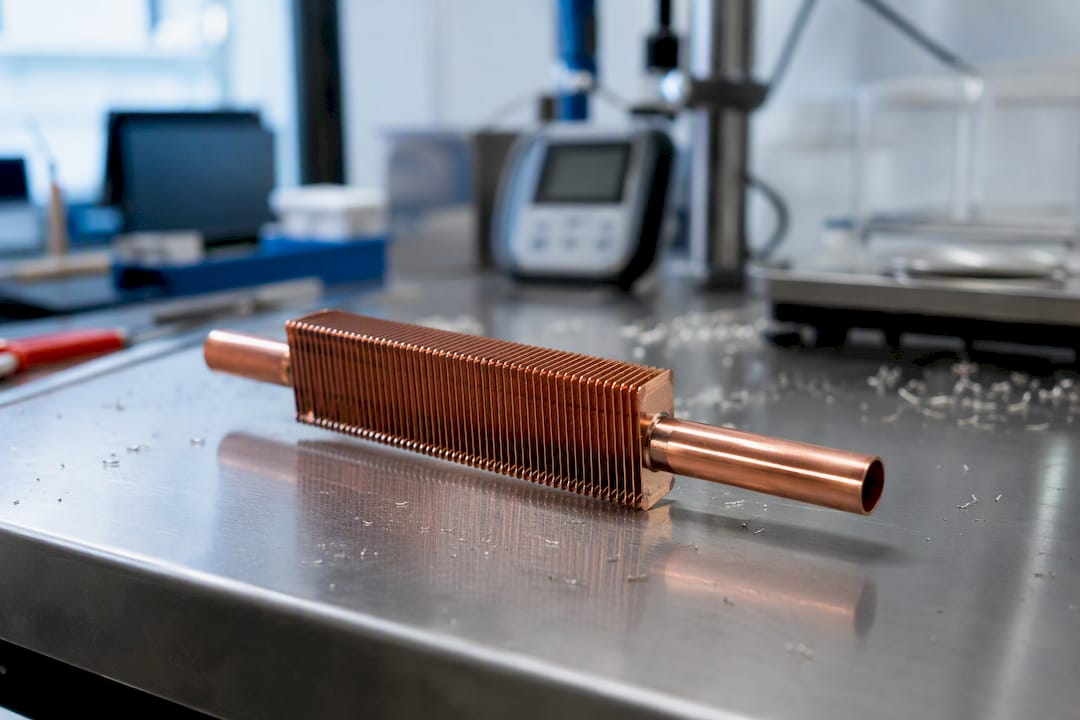
A heat pipe passively moves heat by evaporating a working fluid at a hot interface, pushing that vapor through a hollow core to a cooler zone where it condenses, and pulling the resulting liquid back to the start through capillary action. That closed cycle repeats continuously, without pumps or moving parts, which is why heat pipes function almost like a thermal short circuit rather than a conductor.
The purpose is isothermalization, not refrigeration. A heat pipe cannot cool a component below ambient temperature; it just moves heat somewhere else fast enough that the hot spot stops being hot. Because the fluid transports heat as latent heat rather than through solid-state conduction, effective thermal conductance can run into the thousands of watts per meter kelvin equivalent, an order of magnitude above solid copper in the same geometry.
Evaporator zone: liquid absorbs heat and turns to vapor.
Adiabatic zone: vapor travels with almost no pressure loss.
Condenser zone: vapor gives up latent heat and turns back to liquid.
Wick return: capillary action pulls the liquid back to the evaporator.
Quick stat: the vapor core typically runs only 2 to 5°C hotter at the evaporator than at the condenser, a figure confirmed in NASA’s heat pipe short course. Jewlztech’s simulation engineers treat that number as a diagnostic baseline: if measured ΔT runs well above it, the problem usually lives in the wick or the wall, not the vapor.
Key Takeaways
A heat pipe transports heat almost entirely through latent-heat phase change rather than solid conduction, which is why its vapor-core temperature drop stays in the 2 to 5°C range regardless of transport distance.
Point | Details |
Four-zone cycle | Evaporation, vapor transport, condensation, and capillary return repeat continuously without any moving parts. |
Wick sets the ceiling | Capillary limit is the most common failure mode, and finer pores trade pumping head for higher flow resistance. |
Vacuum integrity is non-negotiable | Non-condensing gas contamination is a leading field failure, especially at low operating temperatures. |
Fluid choice follows temperature | Water, ammonia, methanol, and sodium each own a distinct operating window tied to envelope material compatibility. |
Vapor chambers spread, heat pipes transport | Choose based on whether the source is wide and multi-spot or small and remote from the sink. |
Simulate before you prototype | Jewlztech’s CFD tools couple wall conduction with wick and vapor behavior to catch dry-out risk before hardware cuts. |
Table of Contents
Heat Pipe Working Principle: What’s Inside the Tube
Four components make the whole thing work: an envelope, a wick, a working fluid, and a vapor core. Strip out any one of them and you have a sealed tube that does nothing useful.
The envelope is the outer shell, and its job is containment under vacuum and compatibility with whatever fluid sits inside it. Copper dominates electronics cooling because it pairs well with water and has excellent thermal conductivity at the wall. Aluminum shows up in aerospace and lightweight applications, usually paired with ammonia because aluminum corrodes badly with water over long service life. Stainless steel gets used for high-temperature or corrosive-fluid designs, often with sodium or other alkali metals, where copper would simply degrade.
The wick is the part most engineers underestimate. It has one job: generate enough capillary pressure to pull condensed liquid back to the evaporator against gravity, friction, and whatever orientation the application demands. Three wick families dominate:
Sintered powder wicks offer the highest capillary pumping head because pore radius can be engineered very small, but that same fine structure increases viscous resistance to liquid flow.
Screen mesh wicks are cheaper to manufacture and easier to inspect, with moderate capillary performance and better permeability than sintered powder.
Grooved wicks (axial channels cut into the inner wall) offer the least capillary head of the three but the lowest liquid-flow resistance, which makes them useful in low-gravity or short-pipe applications where capillary pumping demand is modest.
The trade-off is always the same: finer pore structure buys you more pumping force per unit length but taxes you with more resistance to flow. Design work is really an exercise in finding where those two curves cross for your specific heat load and orientation.
Fill fraction and vacuum processing matter more than most students expect walking into their first thermal design course. The tube gets evacuated to remove air, then charged with a precise, small quantity of working fluid, sized so there’s enough liquid to keep the wick saturated without flooding the vapor core. Supplier engineering manuals are blunt about what happens when that vacuum isn’t clean: even trace non-condensing gas accumulates at the condenser end, blocks vapor from reaching the cold wall, and quietly kills low-temperature performance. This is one of the most common field failures, and it’s invisible until you run a temperature map and find an unexplained cold spot.
Pro Tip: Before final seal-off, run a helium leak check and a bake-out cycle on the assembly. A wick that looks intact under a microscope can still carry residual moisture or oxide film that outgasses weeks later and slowly degrades performance. Catching that before shipment is far cheaper than a field return.
The Phase-Change Cycle: Evaporation to Condensation and Back
Every heat pipe runs the same four-stage cycle, over and over, thousands of times a second in steady operation. Understanding each stage separately is the fastest way to diagnose why a design underperforms.
Evaporation happens at the hot end, where heat conducts through the pipe wall into the saturated wick. The liquid there sits at its local saturation temperature, so any added heat goes almost entirely into a phase change rather than raising the fluid’s temperature further. That’s the physical reason heat pipes run so close to isothermal: the fluid is absorbing latent heat, not sensible heat, so the evaporator surface temperature barely climbs even as heat flux rises. Local boiling can occur at higher heat fluxes, and this is where the wick’s structure starts to matter enormously, since vapor bubbles need pathways to escape without disrupting the liquid film feeding the wick.
Vapor transport across the adiabatic zone is deceptively simple physics with dramatic results. The vapor pressure at the evaporator is only marginally higher than at the condenser, but because vapor density is low and vapor velocity can be high, that tiny pressure differential drives an enormous mass flow rate relative to what a comparable pressure drop would push through a liquid. This is the mechanism behind the near-isothermal behavior: a small pressure drop translates into a small temperature drop, because saturation temperature tracks pressure closely for most working fluids. Measured data across a wide range of heat pipe designs shows vapor-core ΔT landing in the 2 to 5°C range under normal load, an order of magnitude smaller than the temperature drop you’d see across an equivalent length of solid metal.
Condensation releases that same latent heat at the cold end, and this is where condenser-side design earns its importance. Fins, cold plates, or a liquid-cooled jacket all exist to pull heat away from the condenser wall fast enough that vapor keeps condensing rather than backing up. A condenser that’s undersized for the heat load becomes the actual bottleneck in the system, even though the evaporator and wick were designed correctly.
Liquid return closes the loop, and how it happens depends entirely on orientation and gravity. Three mechanisms exist:
Capillary-driven return relies purely on wick pore structure and works in any orientation, including against gravity, which is why it dominates electronics and spacecraft applications.
Gravity-assisted return (often called a thermosyphon when capillary structure is minimal) only works when the condenser sits above the evaporator, letting condensate simply flow downhill.
Centrifugal return appears in rotating machinery, where spin force replaces capillary pumping entirely.
Here’s the cycle end to end, for quick reference:
Heat enters the evaporator wall and conducts into the saturated wick.
Working fluid absorbs latent heat and vaporizes.
Vapor flows through the adiabatic zone toward the condenser, driven by a small pressure gradient.
Vapor contacts the cooler condenser wall and releases latent heat, reverting to liquid.
Capillary action, gravity, or centrifugal force pulls the liquid back through the wick to the evaporator.
The cycle repeats continuously as long as heat flows in at the evaporator.
Capillary Pressure and Elevation Limits in Wick Design
Capillary pressure is what makes the whole return mechanism possible, and its governing relationship is straightforward: pumping pressure scales with surface tension and inversely with effective pore radius. Smaller pores generate more capillary head. That’s the entire design lever available to engineers working on wick geometry, and it comes with an unavoidable cost.
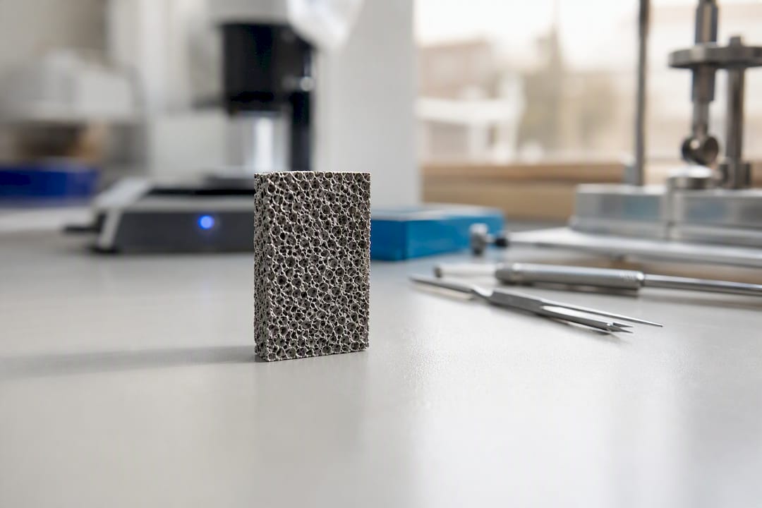
Finer pore structures increase flow resistance through the wick, since the NASA design handbook frames the whole problem as a balance between capillary pumping capacity and the viscous plus dynamic losses the liquid encounters getting back to the evaporator. Push pore size down to maximize pumping head and you simultaneously throttle how much liquid can actually move through that wick per second. Push pore size up for better permeability and you lose pumping force, which limits how far or how high against gravity the pipe can operate.
That trade-off shows up directly in adverse-elevation tolerance. A water-charged copper heat pipe with a conventional sintered or screen wick typically loses meaningful transport capacity once the condenser sits more than a few centimeters above the evaporator against gravity, an order-of-magnitude constraint that matters enormously in orientation-sensitive electronics enclosures. Design margins matter here more than the raw number: manufacturing tolerances and gradual oxidation of the wick surface change wettability over time, which is why conservative designs apply a safety factor to calculated capillary limits rather than running right at the theoretical edge.
A practical wick selection checklist looks like this:
Confirm pore radius against the required capillary head for worst-case orientation, not best-case.
Check permeability data against the peak heat flux the evaporator will actually see.
Verify manufacturing tolerance on pore size, since sintering and screen weaving both carry batch-to-batch variation.
Account for wettability degradation over the expected service life, particularly with copper and water combinations exposed to any oxygen ingress.
Pro Tip: When comparing wick options on paper, don’t just compare capillary head numbers side by side. Model the pressure budget across the whole loop, evaporator wick resistance, vapor path, and condenser wick resistance, because a wick that wins on pumping head can still lose on net transport capacity once flow losses are added in.
Why Heat Pipes Stop Working: The Four Transport Limits
Every heat pipe has a ceiling on how much heat it can move, and that ceiling isn’t a single number, it’s whichever of four physical limits gets hit first for a given design and operating condition.
Capillary limit. This is the most common limit in practice. Once heat flux demands more liquid flow than the wick’s capillary pumping pressure can supply against viscous losses, the wick dries out at the evaporator. Symptom: evaporator temperature spikes sharply while condenser temperature stays flat, a telltale dry-out signature.
Sonic (vapor-flow) limit. At very high heat loads or low operating pressures, vapor velocity can approach the local speed of sound in the vapor phase, choking mass flow the same way a converging nozzle chokes gas flow. This shows up most often in low-temperature or startup conditions and caps how much vapor the adiabatic section can physically pass, regardless of how good the wick is.
Entrainment limit. High vapor velocity moving countercurrent to the returning liquid film can shear droplets off the wick surface and carry them toward the condenser, disrupting the liquid return path. It tends to appear alongside marginal wick designs operating near their capillary ceiling.
Boiling limit. At very high local heat flux, nucleate boiling in the wick can transition to film boiling, where a vapor blanket forms between the wall and the liquid and insulates the evaporator from the fluid entirely. This is the limit most likely to cause sudden, dramatic temperature excursions rather than a gradual rise.
All four limits share one root cause: local heat flux outrunning the fluid’s ability to keep the wick wetted and the vapor path clear. The condenser deserves attention too, since restricting condenser-side heat rejection effectively pushes the whole system closer to its vapor-flow limit even when the evaporator design is fine.
Mitigation strategies follow directly from the mechanism. A capillary-limited design benefits from a wick with larger effective pore structure or reduced flow path length. A boiling-limited evaporator needs its heat flux spread over more surface area, sometimes by switching to multiple smaller heat pipes instead of one larger one. Sonic-limited startups often resolve simply by increasing fill fraction or operating pressure. And staging heat flux, running a device at partial power during startup before ramping to full load, sidesteps transient boiling and sonic issues that only appear during the coldest part of a thermal cycle.
Choosing the Right Fluid for the Job
Working fluid selection is really a temperature-range decision first, and a compatibility decision second. Every fluid has a useful vapor-pressure window, and picking outside that window either starves the pipe of usable vapor pressure or pushes it into unsafe internal pressures.
Water dominates the moderate temperature range, roughly 30°C to 200°C, and is the default choice for electronics cooling because it has outstanding latent heat capacity and pairs naturally with copper envelopes. Evacuated water heat pipes can run above 100°C and have demonstrated practical long-term operation up to around 270°C in well-sealed designs, though most electronics applications never approach that ceiling.
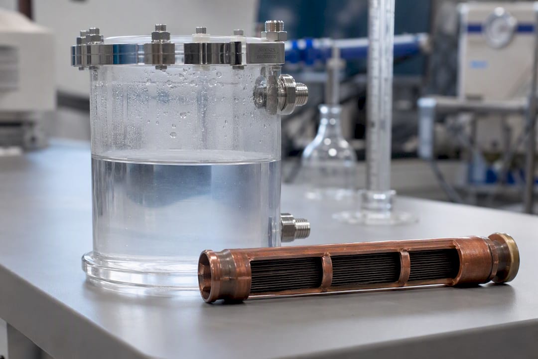
Ammonia handles the sub-zero to moderate range, roughly negative 60°C to 100°C, and is the standard choice for spacecraft thermal straps and aluminum envelopes, since aluminum and water are a poor long-term pairing due to corrosion.
Methanol fills a niche between water and ammonia, useful in the negative 40°C to 120°C band when a lighter, lower-freezing alternative to water is needed without the handling complexity of ammonia.
Sodium and other liquid metals take over at the high end, from roughly 500°C up past 1,000°C, used in nuclear, aerospace re-entry, and high-temperature industrial applications where water and organic fluids would simply decompose or exceed critical pressure.
Working Fluid | Useful Temperature Range | Typical Envelope Pairing |
Ammonia | Roughly −60°C to 100°C | Aluminum |
Methanol | Roughly −40°C to 120°C | Copper, stainless steel |
Water | Roughly 30°C to 200°C (up to ~270°C long-term) | Copper |
Sodium | Roughly 500°C to 1,000°C+ | Stainless steel, refractory alloys |
Envelope and fluid compatibility isn’t optional. Copper and water form a stable, well-understood pairing, which is exactly why it dominates consumer electronics. Aluminum and water generate hydrogen gas through a corrosion reaction over time, which is a textbook cause of the non-condensing gas contamination discussed earlier, so aluminum envelopes almost always pair with ammonia instead. Stainless steel handles sodium and other aggressive high-temperature fluids that would attack copper or aluminum outright.
Internal pressure and fill fraction extend the practical operating window on both ends. Slightly overcharging a low-temperature design raises the minimum operating pressure and helps avoid the sonic limit during cold starts, while a careful fill fraction at the high-temperature end prevents excess liquid from flooding the vapor core and choking transport capacity.
Low-temperature or cryogenic work: fluids like nitrogen or specialized cryogens, always evaluated against triple-point constraints.
Vacuum or space applications: ammonia or water depending on the temperature band, chosen partly for outgassing behavior in hard vacuum.
High-temperature industrial work: sodium, potassium, or lithium, each requiring stainless or refractory envelope materials.
Heat Pipe vs. Vapor Chamber: Matching the Device to the Geometry
The decision between a heat pipe and a vapor chamber comes down to one question: does the heat need to travel to a specific remote point, or does it need to spread across a plane first?
Heat pipes excel at directed, point-to-point transport. A round or flattened pipe carries heat from a concentrated source, a CPU, a power module, an LED array, to a remote heat sink or fin stack, often traveling several centimeters to tens of centimeters in the process. Spacecraft thermal straps are a classic example: heat generated on one panel needs to reach a radiator on another panel, and a heat pipe is the simplest, lightest way to make that journey.
Vapor chambers use the identical evaporation-condensation cycle but flatten the geometry into a thin, wide plane, so heat spreads in two dimensions rather than traveling in one direction. Vapor chambers typically reduce peak source temperature more effectively than a single heat pipe when the source itself is broad or when multiple hot spots need to be evened out before the heat reaches a heat sink. That’s exactly why high-power laptop processors and dense server modules have shifted toward vapor chamber designs over the last decade: the die is wide enough that a single pipe can’t intercept the whole heat flux efficiently.
A rough decision checklist:
Choose a heat pipe when the source is small and concentrated, and the sink is some distance away, since heat pipes are cheaper and simpler for that job.
Choose a vapor chamber when the source is wide, multiple hot spots exist, or peak temperature at the die matters more than transport distance.
Consider multiple heat pipes feeding into a shared fin stack as a middle-ground option when budget rules out a full vapor chamber, since supplier and industry guidance commonly frames this as the practical compromise.
Check package thickness constraints early: vapor chambers need more plan-view area but can be thinner than a bent heat pipe routing around obstacles.
Neither device operates in isolation. The heat pipe or vapor chamber is one link in a chain that includes the source interface material, the spreader, the fin stack, and possibly a liquid loop, and the whole chain determines whether the final junction temperature meets spec.
Pro Tip: Match the device to source geometry before you optimize anything else. Engineers frequently spend weeks tuning wick structure on a heat pipe that was the wrong device choice from the start, when a vapor chamber would have solved the spreading problem in one step. A broader engineering reference on heat transfer applications is worth reviewing before locking in a device family.
A Worked ΔT Check You Can Run by Hand
Before running any simulation, a simplified thermal-resistance network lets you sanity-check whether a heat pipe design is even in the right ballpark. Model the path as four resistances in series: conduction through the evaporator wall, conduction through the saturated wick into the fluid, the (very small) vapor-phase resistance across the adiabatic section, and conduction through the condenser wick and wall back out to the sink.
Here’s a conservative worked example. Assume a copper-water heat pipe, 8 millimeters outer diameter, carrying 15 watts over a 100 millimeter effective length between evaporator and condenser centers, with a sintered wick roughly 0.5 millimeters thick.
Wall conduction (evaporator and condenser): for thin copper wall sections at this power level, wall resistance is typically small, on the order of a few hundredths of a kelvin per watt, and rarely the dominant term.
Wick conduction: the saturated sintered wick, being a mix of metal and fluid, has meaningfully lower effective conductivity than solid copper, so this resistance is usually the largest solid-conduction term in the network, often contributing the bulk of the total ΔT budget outside the vapor core.
Vapor-phase resistance: based on the near-isothermal behavior discussed earlier, this term contributes only the 2 to 5°C vapor-core ΔT regardless of the 100 millimeter transport distance, which is the whole point of using a heat pipe instead of a solid rod.
Sum the network: total ΔT from evaporator wall to condenser wall for a well-designed pipe at this power level typically lands in a low single-digit range plus the vapor contribution, versus a dramatically larger drop a solid copper rod of the same dimensions would show carrying the identical 15 watts.
Parameter | Value |
Heat load (Q) | 15 W |
Effective length (L) | 100 mm |
Outer diameter | 8 mm |
Wick thickness | 0.5 mm |
Vapor-core ΔT (typical) | 2 to 5°C |
Before trusting any hand-calculated result, run these checks:
Confirm evaporator heat flux (watts per square centimeter of wetted evaporator area) sits comfortably below published boiling-limit data for the wick type chosen.
Verify wick permeability against the required liquid mass flow rate for the target heat load.
Check orientation and fill fraction together, since an adverse elevation that was fine at low power can push the design into capillary limit territory at full load.
These checks catch the majority of first-pass design errors before a single CFD run, which is exactly why they belong at the front of any heat exchange design workflow, not as an afterthought once simulation results look wrong.
Where Simulation Fits Into a Verified Design Process
Hand calculations get you a defensible first estimate, but they miss interactions that only show up when wall conduction, wick saturation, and condenser coupling are solved together. A practical verification sequence looks like this:
Start with the hand-calculated thermal-resistance network described above.
Build a 1D heat-pipe model to check capillary, sonic, and boiling limits against the operating envelope.
Run a conjugate CFD simulation that couples solid wall conduction with fluid-phase behavior, catching nonuniform heating and condenser-side bottlenecks that a 1D model can’t see.
Validate with prototype testing before committing to production tooling.
A conjugate simulation catches the case a hand calculation always misses: uneven heat flux across the evaporator footprint driving local dry-out in one corner of the wick, even when the average heat flux looks fine on paper.
Jewlztech’s conjugate heat transfer simulation guide walks through exactly this coupling between solid conduction and fluid-phase modeling, which is the step most hand calculations and simplified 1D models skip entirely.
Common Mistakes Engineers Make With Heat Pipe Designs
Contamination is the failure mode engineers underestimate most. A wick that tests clean on the bench can still carry residual moisture that outgasses weeks into service, and it rarely shows up until a temperature map reveals an unexplained cold spot at the condenser.
Manufacturing variance in wick pore size is the second underestimate. Two pipes from the same production batch can show meaningfully different capillary limits, which is exactly why conservative designs build in margin rather than running at the calculated ceiling.
Orientation effects deserve more attention early in the design process than most first drafts give them. A pipe validated flat on a bench can behave differently once mounted vertically in the final enclosure, so testing at the actual installed orientation isn’t optional.
Run a helium leak check and a thermal cycle test before system integration, every time. And recognize when a heat pipe is overkill: if a solid copper or aluminum spreader gets the job done within a few degrees of your target, the added cost and failure modes of a two-phase device may not be worth it.
How Jewlztech’s Simulation Tools Fit the Design Workflow
Every step in that verification sequence, hand calculation, 1D model, conjugate CFD, prototype test, depends on having simulation tools that can actually couple solid conduction with phase-change fluid behavior instead of approximating it.
Jewlztech’s CFD simulation software is built for exactly that coupling: modeling wall conduction, wick saturation, and vapor-phase transport together so engineers catch dry-out risk or condenser bottlenecks before committing to a prototype run. Engineers using this kind of conjugate approach typically cut the number of physical prototype iterations needed to converge on a working wick design, because the failure modes that used to only show up on the bench, uneven evaporator heating, marginal capillary margin, condenser undersizing, get flagged in the model first. The broader engineering toolkit extends that same workflow to conduction, convection, and radiation problems beyond two-phase devices, with a built-in material property database that removes a lot of the manual lookup work from early-stage sizing.
If your next design review needs evidence rather than a hand-wave, start by running your evaporator heat flux and wick geometry through a conjugate model before you cut metal.
Frequently Asked Questions
What is the basic heat pipe working principle in one sentence? A heat pipe moves heat by evaporating a working fluid at a hot interface, letting vapor travel through a sealed core to a cooler zone where it condenses, then returning that liquid to the hot end through capillary action, gravity, or centrifugal force.
Can a heat pipe cool something below room temperature? No. A heat pipe only relocates heat from one point to another; it always needs somewhere colder than the evaporator to reject heat into, and it cannot generate cooling below ambient on its own.
Why is the temperature drop across a heat pipe so small? Because the vapor is transporting latent heat rather than sensible heat, the pressure difference needed to drive vapor flow is tiny, and saturation temperature tracks pressure closely, which keeps vapor-core ΔT in the 2 to 5°C range under normal load.
What causes a heat pipe to fail or dry out? Dry-out happens when heat flux at the evaporator exceeds what the wick’s capillary pumping pressure can supply against viscous losses, known as the capillary limit; contamination from non-condensing gas and manufacturing variance in the wick can push a design toward that limit sooner than expected.
How is a vapor chamber different from a heat pipe? Both use the same evaporation-condensation cycle, but a vapor chamber spreads heat across a flat plane in two dimensions, while a heat pipe transports heat in one direction between two points; vapor chambers typically lower peak source temperature more effectively when the heat source itself is wide or has multiple hot spots.
Sources
For deeper theory, NASA’s heat pipe short course covers fundamentals and limits concisely. The NASA design handbook goes deeper into capillary theory and classification. Heatpipe.com’s engineering manual offers supplier-level construction guidance, and Jewlztech’s vapor chamber design guide extends this material into spreading applications.
Recommended
Comments