
Run Trustworthy Simulation V&V in 6 Steps for Engineers


Verification ensures you built the model right; validation shows the model is right for the intended use. Both are iterative, not one-time checkpoints, and both get judged against a specific purpose rather than an abstract standard of truth. The goal is never perfect agreement with reality. It’s sufficient confidence to support the decision the model was built to inform.
TL;DR:
Verification confirms that the simulation code accurately solves the intended equations, while validation assesses whether the model outputs match real-world data for the specific application.
Both verification and validation are iterative processes that must be performed throughout model development, with verification focusing on code correctness and validation on physical accuracy.
Achieving numerical convergence through grid refinement and solution stability is crucial before attempting to validate models against experimental data.
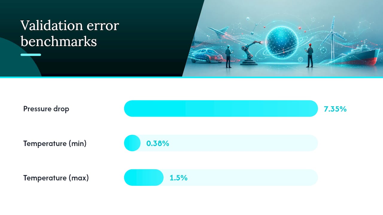
Validation involves comparing outputs to measurements using graphical methods, hypothesis testing, and sensitivity analysis, with errors typically acceptable around 7% for pressure drop and less than 2% for temperature distributions in thermal models.
Proper documentation of assumptions, test procedures, and raw data is essential to establish trust in validation results, supported by standardized guidelines like those from ASME.
Table of Contents
What Is Validation and Verification in Simulation?
Verification and validation, often shortened to V&V, answer two different questions about a simulation. Verification asks whether the code correctly solves the equations you intended to solve. Validation asks whether those equations, once solved correctly, actually represent the physical system you care about.
The distinction traces back to Sargent’s widely cited WSC tutorial, which frames verification as confirming the computerized model matches the conceptual model, while validation substantiates that the model behaves like the real system for its intended purpose. A model can pass verification with flying colors and still be worthless for validation. Bug-free code that solves the wrong physics is still the wrong answer.
This matters more than it sounds like it should. Engineers frequently treat “the simulation ran without errors” as proof of correctness. It’s proof of nothing beyond arithmetic consistency. That’s a validation failure hiding behind a verification success.
Uncertainty quantification (UQ) sits alongside both. Where verification and validation ask “is the model right,” UQ asks “how confident are we, and why.” Together, the three form what practitioners increasingly call VUQ. A validated model without a UQ layer gives you a number; a validated model with UQ gives you a number and an honest error bar.
Verification: Checking That the Code Matches the Math
Verification splits into two flavors. Code verification confirms the software itself is bug free and implements the intended numerical method correctly. Solution verification confirms that a specific run, on a specific mesh and time step, has converged to a stable numerical answer. Both matter, and skipping either is how “it runs fine” becomes “it was wrong the whole time.”
Concrete techniques worth running on every model:
Unit tests on individual subroutines (a conduction solver should reproduce a known analytical slab solution before you trust it in a full assembly).
Desk checks and code walk-throughs, where a second engineer traces the logic line by line against the conceptual model.
Grid-refinement or convergence studies, halving mesh size until key outputs stop changing beyond a set tolerance.
The method of manufactured solutions, where you invent an exact solution, plug it into the governing equations, and confirm the solver reproduces it.
Trace runs and pseudo-random number generator checks for stochastic or Monte Carlo based simulations, per the advanced V&V tutorial from WSC.
Simple unit tests are enough for early development. Reach for full convergence and manufactured-solution studies once the model informs a real engineering decision, especially anything safety-related like pressure vessel wall stress. Document every verification result, even passing ones, and treat unexplained sensitivity to mesh density or time step as an automatic failure requiring investigation before validation even starts.
Pro Tip: Run your convergence study before you touch validation data. A model that hasn’t converged numerically will “validate” against experimental data by pure coincidence, and that agreement will vanish the moment you change a boundary condition.
Validation: Proving the Model Matches Reality
Validation methods split into black-box and white-box approaches. Black-box validation compares overall model outputs to real system outputs without inspecting internal logic. White-box validation checks whether individual submodels and assumptions hold up on their own, which matters when the full system is too complex or expensive to test end to end.
Model validation for heat transfer problems typically leans on a mix of the following, drawn from Sargent’s recommended procedure:
Graphical comparisons of simulated versus measured curves, fast to produce and easy for stakeholders to read.
Confidence intervals around key predicted outputs, ideally reported alongside the point estimate rather than instead of it.
Hypothesis testing (t-tests are common) to check whether observed differences between simulation and experiment are statistically meaningful.
Goodness-of-fit tests when you have enough repeated measurements to build a real distribution.
Sensitivity analysis to identify which inputs actually drive output variance, narrowing where validation effort pays off.
The numbers that matter: a 2024 conjugate heat transfer validation study reported average relative errors of 7.35% for pressure drop predictions and 0.38% to 1.5% for temperature distributions, giving practitioners a real benchmark for what “acceptable” looks like in thermal and CFD work.
Set your acceptable error range before you see the results, not after. Small sample sizes and non-normal error distributions break the assumptions behind standard hypothesis tests, so know your data quality before picking a statistical method.
Choosing the Right Validation Technique for Your Project
Graphical comparisons win on speed and interpretability. You can eyeball a plot of predicted versus measured temperature and spot a systematic bias in seconds, no statistics degree required. Hypothesis tests and confidence intervals win on rigor. They give you an objective threshold instead of a subjective “looks close enough.”
The catch is that rigor has a price. Confidence intervals and t-tests assume a reasonable sample size and, often, roughly normal error distributions. Limited experimental data or skewed error patterns make those tests unreliable at best and misleading at worst. In that situation, nonparametric comparisons or bootstrap confidence intervals hold up better than forcing a classical t-test onto data that doesn’t fit its assumptions.
A practical sequence for most simulation validation work:
Start with exploratory graphical comparisons to catch obvious mismatches early and cheaply.
Run sensitivity analysis to identify which few outputs actually drive your decision, so you don’t waste effort validating variables nobody cares about.
Apply objective statistical tests only to those high-priority outputs, and only when your data supports the test’s assumptions.
Fall back to carefully constructed graphical and expert-judgment comparisons where statistical rigor isn’t achievable.
A Recommended Stepwise V&V Procedure
Sargent’s procedure and the follow-up advanced tutorial both converge on roughly the same sequence. Treat it as a checklist you rerun every time the model changes, not a one-time gate.
Agree on intended use. Define what decision the model supports and which validation techniques are proportionate to that decision’s risk.
Set acceptable accuracy ranges up front, for every output that matters, before you run a single comparison against data.
Check face validity with domain experts on early, exploratory runs. Does the model behave sensibly even before formal testing?
Verify continuously during coding, not as an afterthought once the model looks finished.
Run operational validation on final iterations, across multiple representative operating points, following the WSC advanced tutorial’s guidance on iterative V&V.
Document everything and set review triggers, so hardware changes or new operating regimes automatically prompt a revalidation.
Pro Tip: Write your acceptable error range into the project plan before the first simulation runs. Teams that define “good enough” after seeing results almost always redefine it to match whatever number they got.
Thermal and CFD Validation in Practice
Validating a thermal or CFD model means comparing predictions against multi-point experimental measurements, not a single lucky data point. Instrument uncertainty and repeat-run variability both need to be folded into the comparison, and separating discretization error from genuine model-physics discrepancy requires its own mesh refinement study before you touch the experimental comparison at all.
Metric | Typical validation approach | Reported error range |
Pressure drop | Multi-point flow measurement vs. simulated pressure loss | ~7.35% average relative error |
Temperature distribution | Pointwise thermocouple comparison vs. simulated field | 0.38% to 1.5% relative error |
Mesh convergence | Grid refinement study, independent of experimental data | Output change below chosen tolerance |
Those figures come from a conjugate heat transfer validation exercise, and they’re a useful sanity check: if your pressure drop error is running at 20% while the published benchmark sits near 7%, something in your boundary conditions or mesh deserves a second look. Practitioners should validate across multiple operating points rather than a single flow rate or temperature, since a model tuned to one condition can quietly fail outside it.
Documentation That Builds Trust
A validation result nobody can reproduce is a validation result nobody should trust. Good V&V documentation records assumptions, data provenance, test procedures, raw results, and an honest interpretation of what the numbers mean, following the reporting structure recommended in the advanced WSC tutorial.
Assumptions and simplifications baked into the model.
Where experimental or reference data came from, and its known uncertainty.
The exact test procedure, so someone else can rerun it.
Raw results alongside your interpretation, kept visibly separate.
Citing recognized guidance like ASME’s V&V standards family (V&V 10, V&V 20, V&V 101) signals to reviewers that your process isn’t improvised.
How Jewlz Technologies Supports Practical V&V Work
Running convergence checks and preparing solver-ready material properties takes real tooling, not guesswork. The Jewlz Engineering Toolkit includes free thermal and CFD aids built around exactly these tasks, alongside a built-in property database for temperature-dependent inputs.
Guides on heat sink CFD and CFD boundary conditions walk through the setup choices that verification and validation depend on. The toolkit helps apply the methods above; high-stakes validation involving specialized test rigs still calls for dedicated experimental facilities.
Case Studies Beyond Thermal and CFD
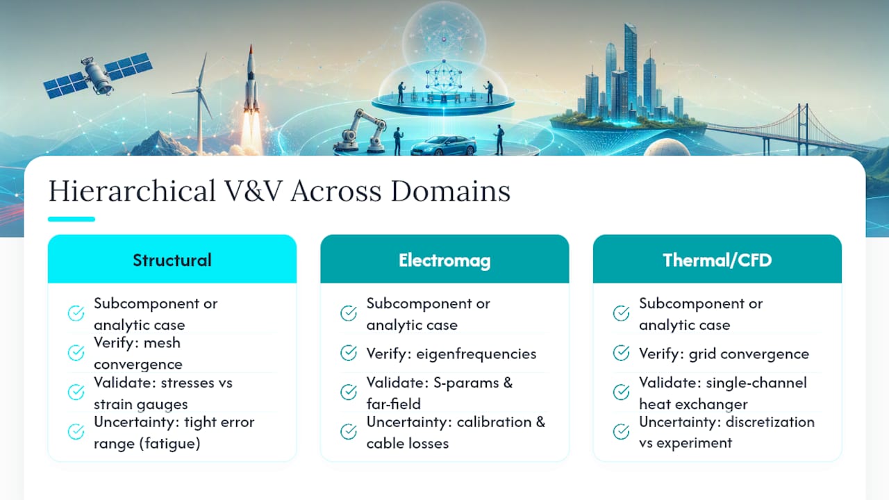
V&V isn’t a thermal specialty. Structural engineers validating finite element models for fatigue life run the exact same playbook: verify the mesh converges under a known analytical loading case, then validate predicted stress concentrations against strain gauge data from a physical test article. The acceptable error range there often tightens considerably compared to thermal work, because a missed stress concentration can mean a cracked bracket rather than a slightly wrong temperature reading.
Electromagnetics simulation follows a parallel path with its own quirks. Verifying an antenna or waveguide solver means confirming it reproduces known closed-form solutions (a resonant cavity’s analytical eigenfrequencies, for instance) before trusting it on a novel geometry. Validation then compares simulated S-parameters or far-field radiation patterns against anechoic chamber measurements, where calibration drift and cable losses introduce their own uncertainty that has to be separated from genuine model error, the same discretization-versus-experiment split thermal engineers deal with.
What ties every domain together is the hierarchical approach: validate subcomponents or simplified configurations before the full coupled system. A structural engineer validates a single bolted joint before trusting the full assembly model. An electromagnetics engineer validates a single antenna element before trusting an array. Thermal and CFD practitioners do the same, validating a single heat exchanger channel before trusting a full multi-pass exchanger model. The physics changes; the discipline doesn’t.
A Practitioner’s Note on Cost and Confidence
Confidence doesn’t scale linearly with effort. Each additional percentage point of certainty costs disproportionately more testing time. Aim for confidence proportionate to the decision at hand, and revalidate after hardware changes, new operating regimes, or software updates rather than chasing an unnecessary final decimal place.
— Joel
Try the Tools Built for This Workflow
Running the checks described above by hand, spreadsheet formulas and manual unit conversions, eats hours that should go toward actual engineering judgment. The Jewlz Engineering Toolkit combines conduction, convection, and radiation models with a built-in property database in one downloadable Excel-based tool, so students and engineers can run convergence checks and prepare solver-ready properties without paid licenses standing in the way.

The toolkit’s Thermal Analysis & Heat Transfer module maps directly onto the validation examples above: variable material properties across a wide temperature range, multiple heat transfer modes in one place, and no separate license fee for the basic tools most V&V work actually needs. If you’re running a pressure vessel or heat exchanger project, the same toolkit extends into CFD and fluid flow simulation and dedicated pressure vessel checks. Head to the Engineering Toolkit page and download the free tools to start applying the convergence and property-mapping steps covered in this guide.
Sources
FAQ
What Is the Difference Between Validation and Verification?
Verification checks whether the simulation code correctly implements the intended equations, essentially confirming you built the model right. Validation checks whether the model’s outputs match real-world behavior for its intended purpose, per Sargent’s tutorial, confirming you built the right model.
How Do You Validate a Simulation Model?
You compare simulated outputs against experimental or reference data using graphical comparisons, confidence intervals, or hypothesis tests, choosing the method that fits your data quality. A 2024 study on conjugate heat transfer models found average errors of 7.35% for pressure drop and 0.38% to 1.5% for temperature, a useful benchmark for what counts as acceptable agreement.
What Are the Main Steps in a Simulation V&V Process?
A practical sequence covers agreeing on intended use and acceptable accuracy ranges, running face validity checks on exploratory runs, verifying the code continuously during development, and performing operational validation on the final model across multiple operating points. Documentation and periodic review triggers close out the process, following the structure in the advanced WSC V&V tutorial.
What Does Validation and Verification Mean in CFD Specifically?
In CFD, verification means confirming the solver has converged through mesh refinement studies and reproduces known analytical solutions where available. Validation means comparing predicted pressure drops and temperature fields against experimental measurements across multiple operating conditions, rather than a single test point.
Does the Jewlz Engineering Toolkit Help With V&V Tasks?
The Jewlz Engineering Toolkit supports verification tasks like convergence checks and offers a built-in property database useful for basic thermal and CFD validation prep. Current prices for the toolkit are available on the Jewlz Technologies site.
Recommended
Comments