
Six Pressure Vessel Head Types: ASME Rules & FEA Checks for Engineers

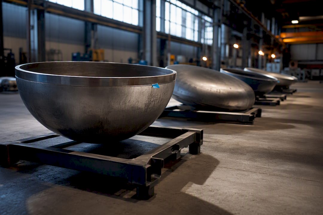
Every pressure vessel head falls into one of six families: hemispherical, 2:1 ellipsoidal, torispherical (ASME F&D), flat, conical or diffuser, and quick-opening closures. Hemispherical heads win on pressure efficiency, 2:1 ellipsoidal heads win on strength-to-profile balance, and torispherical F&D heads win on cost and compactness. Flat and conical heads solve specific handling problems rather than pressure efficiency. ASME Section VIII governs how each is sized, but in practice the head-to-shell junction stress usually decides which one actually gets built.
TL;DR:
Hemispherical heads are optimal for high-pressure vessels due to their low thickness requirement but are costly to form and add significant height.
2:1 ellipsoidal heads balance strength and cost, making them the industry standard for moderate to high-pressure process vessels and refinery drums.
Torispherical heads, with a 6% knuckle rule, are favored for storage tanks because they are easier to form and fit in tight spaces, despite requiring thicker material at the knuckle.
Flat and conical heads solve specific handling and drainage issues and are not pressure-efficient, often requiring heavier material and specialized reinforcement.
Junction stress at the head-to-shell transition, especially at the knuckle, often dictates the vessel design more than code-based minimum thickness calculations.
Table of Contents
Pressure Vessel Head Types: Quick Reference Overview
Before drilling into code clauses and stress math, it helps to see how the common shapes stack up side by side. Each geometry trades thickness, height, and fabrication cost differently, and picking blind from a catalog page is how projects end up with an oversized forging bill.
Hemispherical: half-sphere with radius equal to the shell radius; lowest thickness requirement; highest fabrication cost; used in high-pressure spheres, storage vessels, and submarine hulls.
2:1 ellipsoidal (semi-elliptical): major-to-minor axis ratio of 2:1; moderate thickness; moderate cost; the default choice for refinery drums, air receivers, and most Division 1 vessels.
Torispherical (ASME F&D): crown radius plus knuckle radius, sized by the 6% rule; thicker than ellipsoidal at the same pressure; lowest forming cost; common on storage tanks and process vessels with tight headroom.
Flat: no curvature; requires far greater thickness; cheapest to cut but heaviest per unit strength; used for manways, low-pressure tanks, and covers.
Conical/diffuser: sloped or inverted-dish geometry; thickness depends on half-apex angle; used for hoppers, solids discharge, and aerosol-can bottoms.
Quick-opening closures (QOC): hinged or threaded flat-style closures; built for repeated access rather than thickness efficiency.
Hemispherical Heads: Geometry, ASME Sizing, and Tradeoffs
A hemispherical head is exactly what it sounds like: a half-sphere with a radius matching the shell it caps. That geometry spreads pressure into pure membrane stress with no bending component, which is why hemispherical heads need less thickness than any other shape at the same design pressure. ASME Section VIII sizes them under UG-32(f), and thick-wall regimes trigger the Appendix 1 sphere formulas once the ratio of thickness to radius climbs high enough that thin-shell theory breaks down.
The catch is depth. A hemispherical head adds height equal to the full shell radius, and spinning or forging that dome is expensive. Reserve hemispherical heads for high-pressure spheres, cryogenic tanks, and jobs where every pound of alloy plate matters more than headroom.
2:1 Ellipsoidal Heads: The Industry Default
The 2:1 ellipsoidal head, also called a semi-elliptical head, sets its major axis (the shell diameter) at twice its minor axis (the head depth). That single ratio gives you a profile deep enough to manage bending stress at the knuckle region without the depth penalty of a full hemisphere. ASME sizes it under UG-32(d), and its efficiency sits between hemispherical and torispherical for a given design pressure and material stress).
Most shops press or spin 2:1 heads from a single blank, keeping fabrication cost reasonable. You’ll find this shape on refinery columns, air receivers, and the bulk of Division 1 process vessels rated for moderate to high pressure, because it balances strength, headroom, and cost better than any other standard geometry.
Torispherical and ASME F&D Heads: The 6% Knuckle Rule
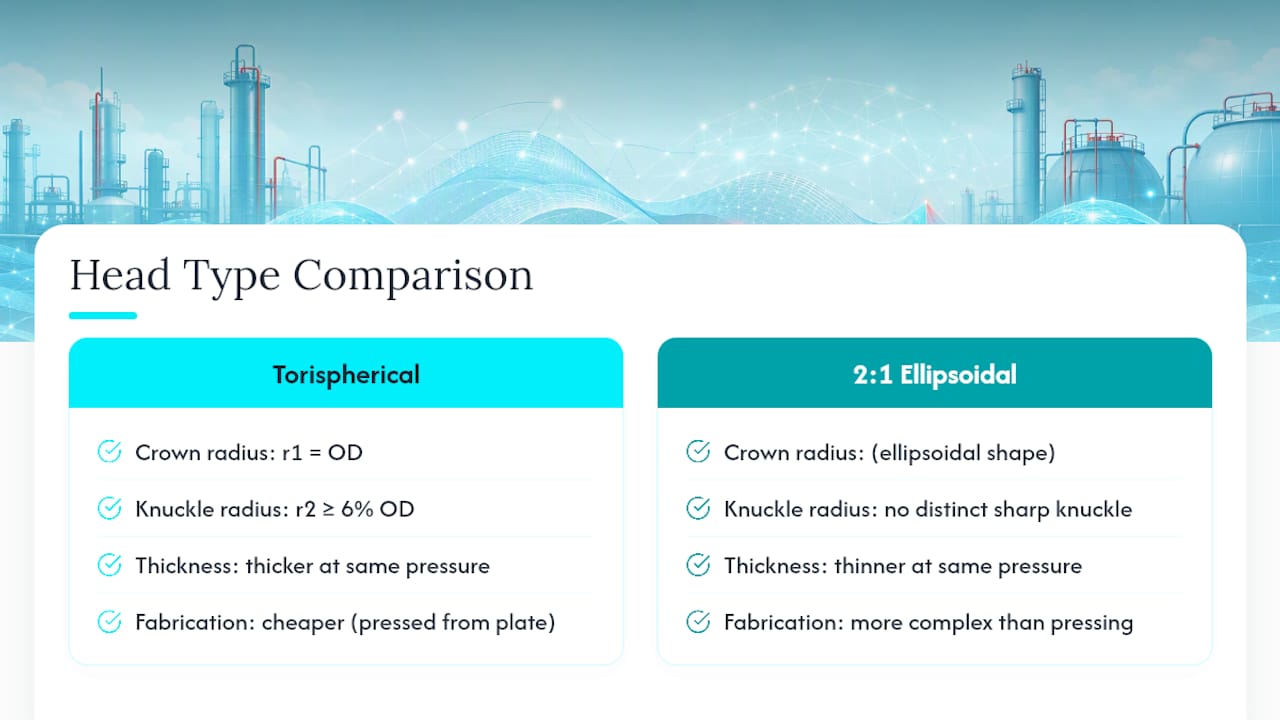
A torispherical head blends two radii: a large crown radius across the dome and a tighter knuckle radius where the head curves down into the shell. The ASME Flanged and Dished (F&D) convention sets the crown radius r1 equal to the outside diameter and requires the knuckle radius r2 to be at least 6% of the outside diameter. That knuckle is also the sharpest stress riser on the whole vessel, so F&D heads typically run thicker than a 2:1 ellipsoidal head at identical pressure.
Fabricators favor torispherical heads anyway because pressing them from flat plate is cheaper and the shallower profile fits in tight vertical space. Process tanks, storage vessels, and moderate-pressure drums lean on this shape constantly. Watch nozzle placement near the knuckle transition. Welds land there more often than anywhere else, and that’s exactly where the geometry is least forgiving.
Flat, Conical, and Quick-Opening Heads for Special Cases
Not every head exists to minimize thickness. Some solve access, drainage, or geometry problems that curved heads can’t touch.
Flat heads: sized under UG-34, these need dramatically more thickness than curved heads at the same pressure. Industry guidance generally restricts them to low-pressure or unpressurized service unless the design adds stiffening rings or heavy reinforcement.
Conical and toriconical heads: the sloped profile drains solids and liquids by gravity, which makes them a natural fit for hoppers and reactors handling slurries. The knuckle where the cone meets the cylinder needs reinforcement to avoid a discontinuity failure.
Diffuser-style heads: an inverted torispherical form shows up in unexpected places, including the bottom of a consumer aerosol can, where the inward dish resists internal pressure while keeping the base compact.
Quick-opening closures: governed by UG-35, these trade thickness efficiency for repeated access. They cost more upfront but save money over years of maintenance on vessels needing frequent internal inspection.
ASME Code Clauses That Govern Head Design
Sizing a head correctly means knowing which clause applies to which geometry, then feeding it the right inputs.
UG-27 sizes the cylindrical shell itself, setting the baseline thickness the heads must match at the joint.
UG-32 covers ellipsoidal, hemispherical, and torispherical heads, with sub-clauses assigning the correct formula and M-factor to each shape.
UG-34 sizes flat heads and covers, which follow a completely different formula built around edge support conditions rather than membrane stress.
UG-37 and UG-45 address nozzle reinforcement and minimum nozzle-neck thickness once openings are cut into any head type.
Appendix 1 and related mandatory appendices take over when thickness-to-radius ratios exceed thin-shell assumptions, common on hemispherical heads at very high pressure.
Every calculation needs design pressure, inside diameter or outside diameter, allowable stress S for the chosen material, joint efficiency E, and a corrosion allowance added on top of the calculated minimum. Once nozzles or flanges attach to the head, cross-check ratings against ASME B16.5 to confirm the mating hardware matches the vessel’s pressure class.
Junction Stress: Why the Knuckle Decides More Than the Code Math
The head-to-shell junction, and specifically the knuckle transition on torispherical and ellipsoidal heads, carries far more bending stress than the smooth crown or the cylindrical shell. A technical review of transition geometry found that inadequate taper at this junction is a recurring driver of fatigue cracking and localized yielding, independent of whether the overall wall thickness satisfies code minimums.
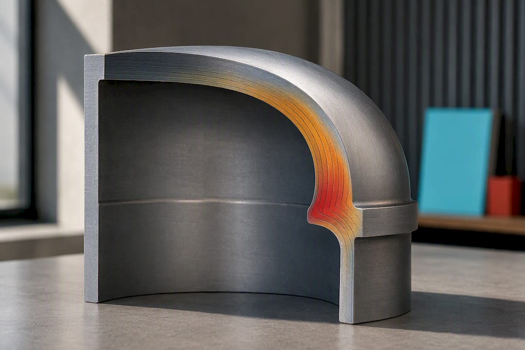
A practical rule of thumb calls for a 3:1 taper where thickness steps down near the junction, smoothing the stiffness transition rather than letting it change abruptly. Hand calculations and UG-32 screening handle standard proportions fine, but nonstandard nozzle clusters, repeated thermal cycling, or knuckle radii near the 6% minimum call for a dedicated finite element analysis instead of a code check alone.
Pro Tip: When you build the FEA model, mesh the knuckle region far finer than the crown or shell, model the actual formed thickness rather than the nominal plate thickness (forming thins the metal at the knuckle), and confirm your nozzle loads and boundary conditions match the real support and piping restraints before you trust the stress output.
Manufacturing Methods, Materials, and Inspection Notes
Dished heads get formed by cold pressing, hot pressing, spinning, or forging, and each method thins the plate differently at the knuckle, which is why fabricators specify a heavier starting plate than the finished minimum calls for. Carbon steel plate like SA-516 Grade 70 covers most moderate-pressure, moderate-temperature work; stainless steel handles corrosive service; aluminum suits lightweight or cryogenic applications; and clad plate gives you a corrosion-resistant surface over a cheaper structural backing.
Specify radiography on head-to-shell welds, confirm post-weld heat treatment (PWHT) triggers based on thickness and material, and set dimensional tolerances on the knuckle radius specifically. That’s the zone most likely to drift out of spec during forming.
A Quick Checklist for Choosing a Pressure Vessel Head
Run through this before committing to a shape on the drawing:
Confirm design pressure and MAWP against each candidate head’s thickness penalty.
Check available height. A hemisphere or deep ellipsoidal head might not fit the plot plan.
Note internal fittings, agitators, or drainage needs that favor a conical or toriconical bottom.
Weigh cost and lead time. F&D heads press faster; hemispherical heads take longer to form and inspect.
Flag fabrication constraints early. Not every shop can spin a hemisphere in the diameter you need; check with Anderson Group Australia — General Engineering - CNC Machinery for heavy machining and large-scale fabrication capabilities.
Treat unusual nozzle clusters or thermal cycling as a red flag that demands a dedicated FEA pass before finalizing the design.
Using Simulation to Verify Head Choice and Junction Stress
Code math tells you a head satisfies minimum thickness. It doesn’t tell you how that head behaves once nozzles, thermal gradients, and real support conditions enter the picture. Jewlztech’s pressure vessel stress analysis guide walks through FEA setups for exactly this gap, and the thermal analysis workflow covers what happens when thermal cycling stacks on top of mechanical loading at the knuckle.
Two habits carry over from the FEA section above: refine your mesh at the knuckle before anywhere else, and always model the formed thickness, not the nominal plate you started with.
Why Engineers Keep Choosing “Good Enough” Over Perfect
Hemispherical heads are the geometric ideal, yet most vessels never use one. Cost, height limits, and forming capacity usually push designers toward torispherical or ellipsoidal heads instead, and that’s a rational tradeoff, not a compromise of quality. Talk to your fabricator early, run a focused FEA on the junction, and let code checks and simulation confirm each other rather than picking one and skipping the other.
— Joel
Verify Head Stress Before It Reaches the Shop Floor
Catalog geometry tells you a head meets minimum thickness. It won’t tell you how that head responds once nozzles, thermal gradients, and knuckle transitions interact under real load, which is exactly the gap most fabrication delays come from. The Jewlz Engineering Toolkit combines pressure vessel simulation with thermal analysis in one place, so you can check a design before it goes out for quotes rather than after a fabricator flags a problem.

There are tools available that allow you to stress-check a head choice without waiting on a full commercial FEA package:
Pressure vessel simulation for common geometries
Coupled thermal analysis for vessels under cyclic or high-temperature service
Calculation reports suitable for sharing with clients or code reviewers
This isn’t a replacement for ASME sizing or vendor forming data. It’s a way to confirm your junction stress assumptions before metal gets cut. Open the engineering toolkit and run your next head geometry through it before you finalize the drawing.
Sources
FAQ
What Is a Type 4 Pressure Vessel?
A Type 4 pressure vessel is a fully composite vessel built around a plastic liner, with no metal in the load-bearing structure. It’s common in hydrogen storage and lightweight gas cylinders where weight savings outweigh the higher manufacturing cost. This classification refers to the shell construction, not the head geometry discussed above, which applies across metal and composite designs alike.
What Are the Different Types of Pressure Vessel Nozzles?
Pressure vessel nozzles include straight pipe nozzles, flanged nozzles, threaded couplings, and reinforced nozzles with added pad or insert plates around the opening. Reinforcement type depends on the hole size relative to the shell or head thickness, sized under UG-37 and UG-45 as noted earlier. Nozzles placed near a head’s knuckle transition typically need extra reinforcement because that zone already carries elevated bending stress.
What Are the Different Types of Pressure Vessels?
Pressure vessels are commonly classified by shell shape (cylindrical, spherical), by construction type (Type 1 through Type 4, from all-metal to full composite), and by service (storage, process, heat exchanger, reactor). Head selection, covered throughout this guide, is one design choice within any of those broader vessel categories rather than a separate classification.
What Is a Type 3 Pressure Vessel?
A Type 3 pressure vessel uses a metal liner, usually aluminum, fully wrapped in a composite overwrap that carries most of the structural load. It sits between the all-metal Type 1/Type 2 vessels and the fully composite Type 4 vessels in both weight and cost. Type 3 construction shows up often in aerospace and high-pressure gas storage applications.
Which Pressure Vessel Head Type Is Cheapest to Fabricate?
Torispherical (ASME F&D) heads are generally the cheapest to press from flat plate, which is why they dominate storage tanks and moderate-pressure process vessels. Flat heads cost less per single head but require so much extra thickness at pressure that the material cost often erases the fabrication savings. Hemispherical heads sit at the opposite end, cheapest in material but most expensive to form.
Recommended
Comments