
TPMS Gyroid: Engineering Guide for Researchers and Scientists

Updated: Aug 27

What is a gyroid TPMS and why does it matter?
The gyroid TPMS is a non-self-intersecting minimal surface with zero mean curvature that repeats continuously in three orthogonal directions, making it one of the most geometrically versatile structures in materials engineering. Unlike a soap film stretched across a wire frame, the gyroid has no boundary. It fills space with a smooth, saddle-shaped topology that divides volume into two interpenetrating, non-connected channels. That geometry is not just mathematically elegant. It is physically useful in ways that flat or cylindrical surfaces simply cannot match.
Before going further, one terminology point deserves attention. “TPMS” appears in two completely unrelated fields. In automotive engineering, TPMS stands for Tire Pressure Monitoring System, a sensor-based safety technology. In materials science and engineering, TPMS stands for Triply Periodic Minimal Surface. This article addresses the latter exclusively. The two share only an acronym.
The gyroid belongs to the broader family of triply periodic minimal surfaces, which also includes the Schwarz P, Schwarz D, and Neovius surfaces. What sets the gyroid apart is its lack of any straight lines or planar symmetry elements, a property that produces its characteristic twisted, continuous channel geometry. That structural feature directly drives performance in applications ranging from bone scaffolds to compact heat exchangers.
Key structural characteristics of the gyroid TPMS:
Zero mean curvature at every point on the surface
Negative Gaussian curvature throughout, producing saddle-shaped geometry
Periodic repetition in three orthogonal spatial directions
No straight lines or mirror planes within the surface
Two interpenetrating, non-connected channel networks
Tunable porosity and surface area through parametric control of the governing equation
Compatibility with additive manufacturing processes including fused deposition modeling (FDM) and selective laser melting (SLM)
Mathematical properties and classification of the gyroid TPMS
The gyroid is formally classified as a Schwarz-G surface, one of several triply periodic minimal surfaces defined by implicit level-set equations. Its characteristic equation takes the form:

sin(x)cos(y) + sin(y)cos(z) + sin(z)cos(x) = f
where x, y, and z are Cartesian coordinates, and f is the isovalue that controls the offset of the surface from its zero-mean-curvature baseline. At f = 0, the equation produces the classical gyroid. Varying f shifts the surface, altering the relative volumes of the two channel networks and, consequently, the porosity of any solid structure derived from it.
TPMS family classification
Surface | Common Name | Straight Lines | Mirror Planes | Typical Porosity Range |
Schwarz-G | Gyroid | None | None | — |
Schwarz-P | Primitive | Present | Present | — |
Schwarz-D | Diamond | None | Present | — |
Neovius | Neovius | None | Present | — |
The gyroid’s absence of straight lines and mirror planes is not a minor geometric footnote. It means the structure has no preferential cleavage planes, which contributes directly to its isotropic mechanical behavior at low relative densities and its resistance to crack propagation along flat interfaces.
Parametric control and surface area
Beyond the standard isovalue manipulation, researchers at Oak Ridge National Laboratory demonstrated that introducing a new parameter p into the characteristic equation allows targeted surface area manipulation. At p = 1, the equation reproduces the classical gyroid. At p = 0.3 (analytically verified at p = 0.3048), surface area reaches a maximum for a fixed unit cell size and number of cells. This parametric approach produced a 20-fold increase in achievable area over a baseline design with a characteristic unit cell size of 25.4 mm, by refining the reference size to 3.175 mm at f = 0.
Pro Tip: When designing gyroid structures for thermal applications, do not treat unit cell size as a fixed variable. Parametric manipulation of the characteristic equation, specifically targeting p = 0.3, yields far greater surface area gains than simply reducing cell size alone.
Key mathematical properties worth knowing:
Mean curvature H = 0 everywhere (defining property of a minimal surface)
Gaussian curvature K < 0 everywhere (negative, saddle geometry)
The surface is a member of the associate family of the Lidinoid surface
Symmetry group: Ia3d (body-centered cubic space group)
No self-intersections at any isovalue within the physical range
The Ia3d space group symmetry has practical consequences. It means the gyroid’s unit cell is body-centered cubic, which influences how the structure responds to loading in different crystallographic directions and why build orientation matters so much in additive manufacturing.
How the gyroid was discovered and developed over time
The gyroid’s history is shorter than its mathematical complexity might suggest. Alan Schoen, a NASA mathematician, first described it in 1970 in a technical report exploring embedded minimal surfaces. Schoen identified it as a surface with no straight lines or planar symmetry, distinct from the Schwarz surfaces that had been known since the 1860s. His work was largely theoretical at the time, and the broader scientific community did not immediately pursue it.
1970: Alan Schoen describes the gyroid in a NASA technical report, identifying it as a triply periodic minimal surface with Ia3d symmetry and no straight lines or mirror planes.
1976: Physicist Elias Helfrich and colleagues begin connecting minimal surface geometry to biological membrane structures, opening a path toward biomimetic applications.
1980s: Crystallographers and physicists study gyroid-like morphologies in block copolymer systems, linking the mathematical surface to self-assembled nanostructures in soft matter.
1990s: Biologists identify gyroid-type structures in butterfly wing scales and in the endoplasmic reticulum of certain cells, establishing the gyroid as a recurring motif in nature.
Early 2000s: Materials scientists begin fabricating gyroid-inspired scaffolds for tissue engineering, motivated by the structure’s high surface area and interconnected porosity.
2010s: Additive manufacturing, particularly SLM and FDM, makes it practical to fabricate metal and polymer gyroid structures with controlled geometry at millimeter and sub-millimeter scales.
2020s: Research expands into gradient-porosity gyroids for bone implants, compact gyroid heat exchangers, and multi-physics simulation frameworks for coupled thermal-mechanical design.
The jump from mathematical curiosity to engineering tool took roughly four decades, and additive manufacturing is what finally closed the gap. Before FDM and SLM, fabricating a gyroid with the geometric fidelity needed for engineering applications was essentially impossible at useful scales.
Mechanical and physical properties of gyroid TPMS structures
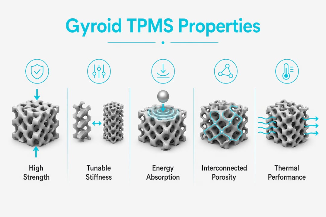
Gyroid TPMS structures offer a combination of high specific strength, tunable stiffness, and superior energy absorption that few other lattice geometries can match across the same density range. The key word is “tunable.” By adjusting wall thickness and relative density, engineers can shift the deformation mode from bending-dominated to stretching-dominated behavior, with direct consequences for stiffness and energy absorption capacity.
Mechanical property ranges
Property | Low Relative Density | High Relative Density | Governing Factor |
Elastic modulus | Low, bending-dominated | Higher, stretching-dominated | Wall thickness, orientation |
Yield strength | Scales with density squared | Approaches bulk material | Relative density |
Energy absorption | High, progressive collapse | Lower per unit mass | Deformation mode |
Anisotropy | Near-isotropic | Orientation-dependent | Build direction |
Mechanical property scaling in gyroid lattices follows Gibson-Ashby models, but accurate stress analysis requires CAD-derived cross-sections rather than idealized geometric assumptions. This matters most at intermediate relative densities, where the transition between bending and stretching regimes produces nonlinear stiffness behavior that simplified models underpredict.
Build orientation has a measurable effect on both stiffness and energy absorption. Research on orientation-driven design shows that axially aligned gyroid orientations yield superior stiffness and energy absorption compared to off-axis configurations, with models designated G1, G3, and G5 consistently outperforming others in experimental and finite element validation.
Key mechanical characteristics:
Specific strength (strength per unit mass) exceeds that of many conventional lattice topologies at equivalent density
Gradient-porosity variants reduce stress shielding in bone implants by matching the elastic modulus of native cortical bone
Progressive, layer-by-layer collapse under compression produces stable energy absorption plateaus
Negative Gaussian curvature inhibits crack propagation along flat planes, improving fracture resistance
Thermal and mechanical performance can be decoupled through independent control of wall thickness and channel geometry
Pro Tip: When specifying a gyroid for load-bearing applications, use CAD-derived cross-sectional data rather than idealized equations to feed your finite element model. The difference between idealized and actual cross-sections becomes significant at wall thicknesses below 1.5 mm, particularly for SLM-fabricated parts.
The gradient-porosity gyroid variant deserves specific attention in biomedical contexts. By varying porosity from the outer cortical-like shell to a more porous interior, designers can replicate the mechanical gradient of natural bone, reducing the stress shielding that causes implant loosening over time.
Where gyroid TPMS structures are actually being used
The gyroid’s combination of high surface area, interconnected porosity, and tunable mechanical properties has driven adoption across several engineering domains. Biomedical and thermal engineering represent the two most active application areas, though aerospace and acoustic insulation are growing rapidly.
Gyroid heat exchangers achieve thermal conductivity as low as 0.023 W/(m·K), which is lower than mineral wool, making them viable for high-performance insulation as well as active heat exchange. In cooling system applications, gyroid-based heat exchangers have demonstrated a 2.2% improvement in coefficient of performance (COP), though this comes with a higher pressure drop that requires careful hydraulic design. For a compact device where pumping power is constrained, that trade-off demands explicit optimization of cell size and porosity rather than a default geometry selection.
In biomedical engineering, gyroid hydrogel scaffolds have demonstrated successful support for HepG2 and HUVEC co-culture, with enhanced endothelial self-assembly driven by the structure’s negative Gaussian curvature. That curvature promotes cell migration and vascularization in ways that flat or cylindrical scaffold geometries cannot replicate. Fabrication fidelity is critical here. A scaffold that deviates from its intended geometry by even a fraction of a millimeter can compromise the biological functionality that the curvature is supposed to provide.
Active application domains:
Bone implants: Gradient-porosity gyroids match native bone stiffness and promote osseointegration
Vascularized tissue scaffolds: Curved geometry drives endothelial self-assembly and neovascularization
Compact heat exchangers: High surface-area-to-volume ratio improves thermal efficiency in constrained spaces
Thermal insulation: Ultra-low thermal conductivity achievable through controlled porosity
Acoustic damping: Interconnected channel geometry attenuates sound across a broad frequency range
Aerospace structures: Lightweight, high-stiffness lattice cores for sandwich panels
Electrochemical cells: High electrode surface area improves reaction kinetics in fuel cells and batteries
For heat exchange applications, the gyroid’s self-supporting network and inherent periodicity make it particularly well-suited to additive manufacturing without support structures, which reduces post-processing cost and preserves internal channel geometry.
The trade-off between permeability and pressure drop is the central design challenge in thermal applications. Designers who optimize solely for surface area will produce a gyroid that transfers heat efficiently but requires disproportionate pumping power. Balancing hydraulic diameter, porosity, and cell size simultaneously is what separates a functional gyroid heat exchanger from a theoretical one.
How engineers design, fabricate, and simulate gyroid TPMS structures
Translating a gyroid from its implicit equation to a manufacturable part requires a specific workflow. The mathematical surface has zero thickness, so the first step is always volumetric quantification: converting the ideal surface into a solid with defined wall thickness, then generating a CAD model that captures both the solid material and the void channels for fluid flow analysis.
Design and fabrication workflow
Define the target geometry using the characteristic equation with selected isovalue f and parametric modifier p.
Generate a volumetric CAD model by offsetting the zero-thickness surface to the desired wall thickness (typically 1–2 mm for additive manufacturing).
Validate the CAD model against target porosity, surface area, and hydraulic diameter specifications.
Select the fabrication method based on material and resolution requirements: FDM for polymers, SLM for metals, binder jet printing for ceramics and high-temperature alloys.
Run finite element analysis (FEA) using CAD-derived cross-sections to predict mechanical response under target loading conditions.
Perform computational fluid dynamics (CFD) simulation to characterize pressure drop and heat transfer coefficient across the operating flow range.
Iterate on p, f, wall thickness, and unit cell size to meet combined mechanical and thermal performance targets.
For mechanical simulation, COMSOL Multiphysics is widely used for coupled thermal-structural analysis of gyroid lattices, enabling engineers to model conduction, convection, and structural deformation within a single simulation environment. Its parametric sweep capability is particularly useful for exploring the effect of wall thickness and orientation on stiffness without rebuilding the geometry from scratch each time.
The AutoCAD 3D solid modeling workflow is a practical starting point for engineers transitioning from the mathematical gyroid model to a manufacturable CAD geometry, particularly when working with implicit surface representations that standard solid modeling tools do not handle natively.
Pro Tip: For FDM-fabricated gyroids, orient the build so that the primary loading axis aligns with the direction of highest stiffness identified in your FEA. Axially aligned orientations (G1, G3, G5 in published literature) consistently outperform off-axis configurations in both stiffness and energy absorption.
Fabrication method comparison
Method | Material Compatibility | Resolution | Surface Fidelity | Best For |
FDM | Polymers, composites | Moderate | Moderate | Prototyping, biomedical scaffolds |
SLM | Metals, alloys | High | High | Structural, thermal applications |
Binder jet printing | Ceramics, metals | High | High | High-temperature heat exchangers |
Stereolithography | Photopolymers | Very high | Very high | Microfluidic, optical applications |
Key design parameters engineers control:
Unit cell size L (affects hydraulic diameter and surface area density)
Isovalue f (shifts porosity between the two channel networks)
Parametric modifier p (controls surface area growth beyond characteristic values)
Wall thickness w (determines mechanical stiffness and manufacturing feasibility)
Build orientation (drives mechanical anisotropy and surface finish quality)
For CFD simulation of gyroid heat exchangers, the mesh generation step is often the most time-consuming part of the workflow. The smooth, curved geometry of the gyroid requires a high-quality unstructured mesh to capture boundary layer effects accurately, and coarse meshing at the channel walls will underpredict the heat transfer coefficient by a measurable margin.
Frequently asked technical questions about gyroid TPMS
What exactly is a TPMS gyroid, and how does it differ from automotive TPMS? In materials science, TPMS stands for Triply Periodic Minimal Surface. The gyroid TPMS is a mathematically defined surface with zero mean curvature that repeats in three orthogonal directions. Automotive TPMS refers to Tire Pressure Monitoring Systems, a completely unrelated sensor technology. The two share only the acronym.
How does the gyroid differ from other TPMS types like Schwarz P or Schwarz D? The gyroid has no straight lines and no mirror planes, unlike the Schwarz P and Schwarz D surfaces. Its Ia3d space group symmetry produces a more isotropic mechanical response at low relative densities, and its twisted channel geometry generates higher surface area per unit volume than the Schwarz P at equivalent porosity.
What mechanical advantages do gyroid structures offer over conventional lattices? Gyroid lattices combine high specific strength, progressive energy absorption, and near-isotropic behavior at low density. Gradient-porosity variants can match the elastic modulus of cortical bone, reducing stress shielding in implants. Build orientation can be used to tune anisotropy deliberately for applications where directional stiffness is an asset.
How is a gyroid TPMS fabricated at engineering scales? FDM and SLM are the two dominant methods. FDM suits polymer prototypes and biomedical scaffolds; SLM produces metal parts with higher geometric fidelity for structural and thermal applications. Both require a volumetric CAD model derived from the implicit surface equation, with wall thickness added before slicing.
Which applications benefit most from gyroid TPMS geometry? Compact heat exchangers, bone implants, and vascularized tissue scaffolds gain the most from gyroid geometry. The high surface-area-to-volume ratio drives thermal performance; the negative Gaussian curvature promotes cell adhesion and vascularization; and the tunable porosity allows mechanical matching to biological tissue.
How Jewlztech supports gyroid TPMS simulation and design
Designing a gyroid structure that performs as predicted requires more than a good CAD model. The coupled thermal, fluid, and structural physics that govern gyroid performance in real applications demand simulation tools that can handle multiple heat transfer modes simultaneously, variable material properties, and the geometric complexity of a triply periodic surface.
Jewlztech’s Thermalysis Toolkit is built for exactly this kind of multi-mode thermal analysis. It covers conduction, convection, and radiation within a single environment, supports variable material properties across a wide temperature range, and includes a built-in material property database that eliminates the manual lookup step that slows down iterative design. For engineers working on gyroid heat exchangers or thermally loaded implants, that combination of modes and material data in one downloadable tool shortens the path from geometry to validated thermal prediction.
The Thermalysis Toolkit supports physics-based thermal simulations, CFD analysis, and pressure vessel calculations through an integrated web-based engineering platform, giving engineers a practical starting point for gyroid thermal-mechanical design without requiring a dedicated simulation license.
Toolkit capabilities relevant to gyroid TPMS analysis:
Conduction analysis for solid gyroid walls and substrate interfaces
Convection modeling for fluid flow through gyroid channel networks
Radiation analysis for high-temperature gyroid applications in aerospace and energy systems
Variable material property support across the full operating temperature range
Built-in property database covering metals, polymers, and ceramics used in gyroid fabrication
CFD simulation for pressure drop and heat transfer coefficient prediction in gyroid heat exchangers
Pressure vessel simulation for gyroid-core structural components under internal pressure loading
For engineers who want to explore active versus passive cooling configurations with gyroid heat exchangers, the toolkit’s convection and CFD modules provide the thermal-hydraulic data needed to make that decision quantitatively rather than by rule of thumb.
Pro Tip: Use the Thermalysis Toolkit’s built-in material database to run a sensitivity analysis on thermal conductivity before committing to a fabrication material. For gyroid heat exchangers, the difference between a polymer and an aluminum alloy wall can shift the effective thermal conductivity of the structure by an order of magnitude, even at identical geometry.
The Thermalysis Toolkit is available as a web-based engineering analysis platform, making advanced thermal simulation accessible without requiring a dedicated high-cost simulation license. For research groups and engineering teams that need rapid iteration on gyroid thermal design parameters, that accessibility supports faster engineering design decisions.

Computational modeling and simulation techniques for gyroid TPMS
Computational modeling of gyroid TPMS structures spans three coupled physics domains: structural mechanics, fluid dynamics, and heat transfer. Each domain has its own mesh requirements, boundary conditions, and validation challenges, and the gyroid’s complex geometry amplifies all of them.
Finite element analysis for mechanical prediction
FEA of gyroid lattices starts with the CAD-derived solid model. Idealized geometric assumptions, such as uniform circular cross-sections, introduce errors that grow as wall thickness decreases. Accurate stress analysis requires cross-sections extracted directly from the CAD geometry, particularly at the nodes where gyroid walls intersect. Gibson-Ashby scaling laws provide a useful first-order estimate of elastic modulus and yield strength as a function of relative density, but they do not capture the orientation dependence that additive manufacturing introduces. For that, a full 3D FEA with orientation-specific boundary conditions is necessary.
COMSOL Multiphysics handles this workflow well. Its structural mechanics module accepts imported CAD geometries, supports anisotropic material definitions, and can run parametric sweeps over wall thickness and orientation simultaneously. Researchers validating gyroid mechanical models against experimental data typically use COMSOL for the simulation side, with compression testing on SLM-fabricated specimens for experimental comparison.
CFD for thermal-hydraulic performance
CFD simulation of gyroid heat exchangers focuses on two outputs: the heat transfer coefficient at the channel walls and the pressure drop across the device. Both depend strongly on the local channel geometry, which changes continuously along the gyroid surface. A mesh that resolves the boundary layer at the wall is non-negotiable for accurate heat transfer prediction. Typical practice uses a structured boundary layer mesh near the walls with an unstructured tetrahedral mesh in the channel interior.
The pressure drop trade-off identified in gyroid heat exchanger studies is a direct output of CFD: higher surface area from parametric manipulation increases heat transfer but also increases flow resistance, raising pumping power requirements. CFD quantifies that trade-off explicitly, allowing designers to find the porosity and cell size combination that maximizes COP for a given pumping power constraint.
Multi-physics coupling in COMSOL Multiphysics
COMSOL Multiphysics enables fully coupled thermal-structural simulation, where temperature-dependent material properties feed back into the structural analysis and vice versa. For gyroid structures operating under simultaneous thermal and mechanical loading, such as heat exchanger cores in aerospace applications, this coupling is not optional. Thermal expansion of the gyroid walls under operating temperature gradients generates stresses that a purely mechanical model will miss entirely.
The workflow in COMSOL typically proceeds as follows: import the CAD geometry, define material properties from the built-in or custom database, set boundary conditions for both thermal and structural physics, mesh the geometry with physics-controlled meshing, and run the coupled solver. Post-processing in COMSOL allows direct extraction of stress distributions, temperature fields, and fluid velocity profiles on the same geometric model, which simplifies the comparison between thermal and mechanical performance predictions.
Key Takeaways
The gyroid TPMS delivers a combination of tunable geometry, high surface area, and coupled thermal-mechanical performance that no other single lattice topology currently matches across biomedical, thermal, and structural applications.
Point | Details |
Build orientation drives performance | Axially aligned orientations (G1, G3, G5) yield the highest stiffness and energy absorption in gyroid lattices. |
Parametric control unlocks surface area | Setting p = 0.3 in the characteristic equation produces up to a 20-fold increase in surface area compared to baseline designs. |
Thermal efficiency has a hydraulic cost | Gyroid heat exchangers improved COP by 2.2% but require explicit optimization of porosity and cell size to manage pressure drop. |
Curvature drives biological performance | Negative Gaussian curvature promotes endothelial self-assembly and vascularization in tissue engineering scaffolds. |
CAD fidelity is non-negotiable | Accurate FEA and CFD predictions require CAD-derived cross-sections, not idealized geometric approximations. |
The gyroid’s real promise is still ahead of us
The gyroid TPMS has been mathematically known for over 50 years, but the engineering community has only had practical access to it for about a decade, since additive manufacturing reached the resolution and reliability needed to fabricate it at useful scales. That gap between mathematical discovery and engineering adoption is closing fast, but the field is still in an early phase of understanding what the gyroid can actually do when you push its parameters deliberately rather than accepting default configurations.
What strikes me most about the current research is how often the most important performance gains come not from the geometry itself but from the parametric control of that geometry. The 20-fold surface area increase achievable through p-value manipulation is a good example. Most published gyroid heat exchanger studies use the characteristic equation at p = 1. The researchers who pushed p to 0.3 found a maximum that the standard approach would never reach. That kind of result suggests there is still substantial performance sitting untapped in the parameter space, waiting for engineers who are willing to treat the governing equation as a design variable rather than a fixed formula.
The biomedical side has a different kind of gap. The curved Gaussian curvature of the gyroid promotes vascularization in ways that flat scaffold geometries cannot, but fabrication fidelity remains the limiting factor. A scaffold designed to exploit that curvature effect needs to be manufactured with geometric accuracy at the sub-millimeter scale, and not every additive manufacturing process can deliver that consistently. As SLM and binder jet printing continue to improve in resolution and repeatability, the biological performance ceiling for gyroid scaffolds will rise with them.
Multi-physics simulation is where I see the next major shift in how engineers work with gyroid structures. Right now, most design workflows treat thermal and mechanical performance as sequential problems: optimize the geometry for heat transfer, then check if it survives the mechanical loading. Fully coupled thermal-structural simulation, as COMSOL Multiphysics enables, changes that to a simultaneous optimization. The tools exist. The barrier is mostly workflow familiarity and computational cost, both of which are dropping.
The gyroid is not a solution looking for a problem. It is a geometry with specific, well-documented advantages in high-surface-area, high-strength, and biologically active applications. The engineers who will get the most out of it are the ones who understand its parameter space deeply enough to design for a specific performance target rather than selecting it because it looks sophisticated.
Recommended
Comments