
When PCM Thermal Management Works (and When It Doesn't)

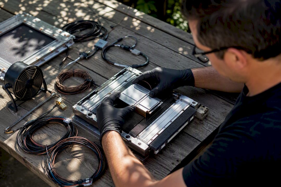
PCM thermal management is a passive latent-heat buffer that absorbs transient heat spikes at a nearly constant temperature, then releases that heat later or during idle periods. It shines in peak-shaving and intermittent-load scenarios. It is not a replacement for active cooling when your system dumps sustained high heat flux hour after hour.
The mechanism is simple: a phase change material absorbs latent heat during its solid-to-liquid transition, holding temperature nearly flat while it melts. That flat plateau is what makes PCM valuable for electronics and battery packs that see bursts of power rather than continuous full-load operation.
The right question isn’t “does PCM cool my system?” It’s “does my system generate heat in bursts I can buffer, or in a steady stream I need to move?”
A few practical anchors before you go further:
Ideal use case: intermittent or cyclic loads, peak shaving, noise-sensitive or power-constrained enclosures.
Quick sizing hint: required PCM mass scales with the energy you need to absorb divided by the material’s heat of fusion.
Watch this first: thermal conductivity. Most PCMs conduct heat poorly, and that bottleneck shapes almost every design decision downstream.
Jewlztech built the Thermalysis Toolkit around exactly this kind of transient, multi-mode heat transfer problem, and it comes up again later as a way to validate these designs before you cut metal.
Key Takeaways
PCM thermal management works by using latent heat to flatten temperature spikes during intermittent loads, but it degrades fast under sustained high power and needs conductivity enhancers, careful containment, and transient simulation to perform reliably.
Point | Details |
Match load profile first | Confirm your load is intermittent, not continuous, before committing to PCM as a primary strategy. |
Conductivity is the bottleneck | Pair PCM with fins, metal foams, expanded graphite, or nanoparticles to move heat into the bulk. |
Size with a margin | Estimate mass from required energy divided by heat of fusion, then add 20 to 30% margin. |
Plan for recharge | Resolidification time and ambient sink temperature often limit real-world cycle rate more than melting does. |
Simulate before building | Use Jewlztech’s Thermalysis Toolkit for electro-thermal coupling and moving-boundary simulation to validate melt fraction and peak-temperature predictions before prototyping. |
Table of Contents
How PCM Thermal Management Actually Works
The core mechanism is latent heat: as a PCM melts, it absorbs energy without a corresponding temperature rise, because that energy goes into breaking molecular bonds rather than raising kinetic energy. That plateau, sometimes just a degree or two wide, is the entire value proposition. A component sitting behind a PCM buffer sees a flattened temperature curve instead of a spike.
Inside the material, melting doesn’t happen all at once. A moving melting front advances from the heat source outward. This is a classic Stefan problem in thermal physics: the boundary between solid and liquid phases shifts over time, and its position determines how much PCM is actively absorbing heat at any moment versus sitting solid and idle. Get the geometry wrong and you can have PCM three centimeters from the heat source that never melts at all during your load event.
Three heat-transfer modes govern behavior here: conduction inside the PCM itself (slow, since most PCMs conduct poorly), convection at the melted liquid’s free surfaces, and conduction from the heat source into the PCM through whatever containment or contact interface separates them. That last one deserves attention many designs skip.
Melting front position dictates how much PCM is actually working at any given moment.
Contact resistance at the source-to-PCM interface can dominate total thermal resistance.
Liquid-phase convection inside the melted region speeds heat spreading, but only after melting begins.
Moving-boundary behavior must be captured in simulation, not approximated with a lumped model.
A useful diagram to sketch for your own design: heat source at one edge, a melting front curving inward, solid PCM ahead of it, and liquid PCM (with faint convection arrows) behind it.
PCM Classes and the Properties You Need to Specify
Four PCM classes cover nearly every practical application: organic paraffins, inorganic salt hydrates, eutectic mixtures, and composite or microencapsulated PCMs. Each brings a distinct set of trade-offs, and comprehensive PCM reviews document how encapsulation and composite fillers shift those trade-offs in practice.
Before you specify a PCM in a material sheet or feed it into a simulation, you need real numbers for each of these:
Property | Why it matters |
Melting point ™ | Must sit inside your actual operating temperature window |
Heat of fusion (ΔHfus) | Determines energy absorbed per unit mass during phase change |
Specific heat (cp) | Governs sensible heat storage before and after melting |
Thermal conductivity (k) | Sets how fast heat actually reaches the PCM bulk |
Density (solid and liquid) | Affects volume, mass, and packaging allowances |
Volumetric expansion | Drives containment design and leak risk |
Supercooling tendency | Determines whether the PCM resolidifies at a usable temperature |
Flammability | Affects safety classification and enclosure design |
Organic paraffins are chemically stable and cycle well over thousands of cycles, but their conductivity is low and they carry real flammability concerns. Salt hydrates pack more energy per volume and cost less, but they’re prone to supercooling and phase separation over repeated cycles. Eutectics let you tune melting point precisely by blending components, at the cost of more complex qualification testing. Composite and microencapsulated PCMs trade some latent capacity for dramatically better handling, conductivity, and containment.

How to Integrate PCM Into Electronics and Battery Designs
Four integration patterns cover most real products: encapsulated microPCM blended into a substrate or potting compound, PCM-packed heat sinks bolted to a component, PCM-lined enclosures that buffer whole systems, and immersion or heat-exchanger designs where PCM surrounds a battery module directly.
Each level suits a different problem:
Component-level (microPCM): best for hot spots on individual chips or small modules; low thermal mass, limited total buffering capacity.
Module-level (PCM heat sinks): good middle ground for power electronics or battery modules with cyclic duty; moderate mass and volume penalty.
Pack-level (PCM-lined enclosures, immersion): best for whole battery packs or equipment cabinets; largest thermal mass, but adds significant weight and requires careful containment engineering.
Containment is where designs actually fail. PCMs expand on melting, sometimes by 10% or more in volume, so rigid enclosures need expansion allowance or they’ll crack, deform, or force PCM past seals. Chemical compatibility matters too: some salt hydrates are corrosive to aluminum, and some organic PCMs can attack certain elastomer seals or interact poorly with battery electrolytes if containment fails. Enclosure-level PCM designs also need a recharge path, since resolidification often happens more slowly than melting and depends heavily on ambient sink temperature.
Pro Tip: Add a small nucleating agent to salt-hydrate PCMs during formulation to reduce supercooling. Without it, a PCM rated to freeze at 25°C can stay liquid down to 10°C or lower, silently eating into your next duty cycle’s buffering capacity.
Plan airflow or a light active-assist path specifically for resolidification. A PCM that melts beautifully during a power spike but never fully resolidifies before the next spike is a PCM that stops working after the first cycle.
For battery-specific integration decisions, including melting-point selection tied to real duty cycles, see this EV battery thermal management guide.
Fixing the Thermal-Conductivity Bottleneck
Low intrinsic thermal conductivity is the single biggest limitation in PCM systems, and thermal-conductivity enhancers are the proven fix. Four approaches dominate practice:
Metal fins: cheap, well understood, and easy to manufacture, but they displace PCM volume and reduce total latent storage.
Metal foams (copper, nickel, aluminum): experimental data shows meaningful reductions in peak temperature and faster resolidification in several configurations, at the cost of added weight and manufacturing complexity.
Expanded graphite: raises effective conductivity substantially with a relatively small volume penalty; a common choice when mass matters more than cost.
Nanoparticle fillers: flexible for tuning conductivity, but dispersion stability over repeated melt cycles is a real long-term concern.
Pro Tip: Treat filler fraction as a curve, not a switch. Conductivity gains taper off past a certain loading percentage, while latent storage loss keeps climbing linearly. Most designs land in a sweet spot well before 20% filler by volume, not at the maximum a supplier can pack in.
Watch for mechanical and chemical compatibility too: high filler loadings can make composite PCMs brittle, and some metal foams corrode in contact with certain salt hydrates over hundreds of cycles.
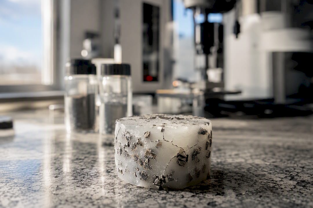
Modeling PCM Systems for Reliable Predictions
Electro-thermal coupling paired with transient simulation is not optional for PCM design work. A static thermal model will miss the moving melting front entirely, and it can’t capture how a battery cell’s own heat generation changes as current and internal resistance shift with state of charge.
A workable methodology checklist:
Choose a numerical approach that handles moving boundaries (enthalpy method or apparent heat capacity method are common, practical choices).
Build a mesh strategy fine enough near the melting front to capture its motion without making the whole model impractically slow.
Feed in temperature-dependent, variable material properties rather than fixed constants; PCM conductivity and density both shift meaningfully between phases.
Couple the thermal model to a real power profile or a physics-based cell heat-generation model rather than a flat average load.
Validation metric | What it tells you |
Peak temperature reduction | Whether the PCM is actually flattening your worst-case spike |
Melt fraction vs. time | How much of the PCM is engaged during a given load event |
Resolidification time | Whether the PCM recovers before the next cycle starts |
Thermal uniformity | Whether hot spots persist despite average temperature looking fine |
The Thermalysis Toolkit from Jewlztech was built around this exact workflow, with variable material properties and a built-in property database that removes a lot of the manual lookup work from setting up a transient PCM simulation.
Choosing the Right PCM: A Practical Checklist
Start with one rule: match the PCM’s melting range to your actual operating window, then verify conductivity and cycling life can support your duty cycle. Everything else is refinement.
A rough sizing heuristic for required PCM mass:
Estimate the energy you need to absorb during your worst-case transient event, in joules.
Divide by the PCM’s heat of fusion (in J/kg) to get a first-pass mass estimate.
Add margin, typically 20 to 30%, to account for melting-front lag and incomplete phase-change utilization.
This assumes the PCM fully melts during the event and ignores sensible heat contribution, so treat it as a starting point for simulation, not a final number.
Run through this before locking a material choice:
Operating temperature window and how tightly the PCM’s melting range needs to sit inside it.
Required buffer energy in joules, tied to your actual worst-case load profile.
Duty cycle shape: truly intermittent, or does it drift toward continuous?
Containment and chemical compatibility with adjacent materials.
Flammability rating and any enclosure implications.
Manufacturability at your production volume.
Where PCM Delivers, and Where It Falls Short
Three application buckets cover most PCM deployments: electronic enclosure buffering, component-level heat sinks on individual chips or modules, and battery pack thermal management. In each, the PCM’s job is the same: shave peak temperatures and extend the safe operating window before active cooling has to intervene.
Battery packs with PCM plus conductivity enhancers have shown peak cell temperature reductions of roughly 5 to 15°C, with some reports of extended cycle life alongside those gains.
Electronic enclosures using PCM absorb daytime heat loads and release them overnight, which works well for equipment with a predictable daily cycle but poorly for equipment running flat out around the clock.
Component-level PCM heat sinks handle brief, moderate-power bursts effectively but lose ground fast as power climbs.
That last point has real data behind it: one experimental study found the temperature-rise penalty for a non-finned PCM sample grew from about 56.7% at 4 watts to roughly 89% at 12 watts. That’s the clearest evidence available that PCM alone degrades quickly as sustained power flux rises, and it’s exactly where hybrid active-passive architectures earn their complexity.
Failure Modes and Safety Considerations You Can’t Skip
Every PCM system carries the same handful of reliability risks, and each one needs an explicit line item in your design spec, not an assumption that it “probably won’t happen.”
Leakage: address with robust containment and expansion allowance sized to the PCM’s actual volumetric expansion.
Supercooling: mitigate with nucleating agents so the PCM resolidifies near its rated temperature instead of drifting well below it.
Phase separation: a known issue in salt hydrates over repeated cycles; composite or encapsulated formulations reduce it.
Flammability: organic PCMs in particular may need flame-retardant additives or isolation from ignition sources.
Interface thermal resistance: engineers routinely under-specify this. Contact resistance between component and containment can dominate total system resistance, so plan conductive bridges like metal inserts or soldered plates rather than relying on incidental contact.
Pro Tip: Run a compatibility test between your candidate PCM and any adjacent battery casing or electrolyte material before committing to a formulation. A material that performs beautifully in isolation can corrode a casing or degrade a seal over a few hundred cycles. For component and die-level concerns specifically, conference research on PCM-based thermal management walks through the die-level failure modes in more depth.
PCM-First or Active-First: A Rule of Thumb
Pick PCM-first when your load is genuinely intermittent and you’re under strict noise, energy, or weight budgets. Pick active-first the moment your heat flux is sustained and high, because no amount of latent capacity buys you out of a continuous energy problem.
The most underrated design move in this space isn’t picking the perfect PCM. It’s sizing an active system down to handle just resolidification, rather than the full worst-case load, and letting PCM absorb the spikes an active system would otherwise be oversized to chase. Read more on that trade-off in this active versus passive cooling decision guide. Verify melting-front behavior in simulation before you ever build a prototype; that’s where most PCM designs quietly go wrong.
Validate Your PCM Design Before You Cut Metal
The Thermalysis Toolkit handles the electro-thermal coupling and moving-boundary simulation that a PCM design actually needs, with variable material properties and a built-in property database so you’re not hunting down heat-of-fusion values from five different data sheets.

In practice, engineers using the toolkit for PCM work tend to follow the same sequence:
Import a real power trace or duty cycle instead of a flat average load.
Specify PCM properties (melting point, heat of fusion, conductivity) directly from the built-in database or your own material sheet.
Run a transient electro-thermal simulation that tracks the melting front over the full event.
Export melt-fraction and peak-temperature graphs to compare against your validation metrics.
That workflow replaces a stack of spreadsheet approximations with a single transient model you can actually defend in a design review. If you’re sizing a PCM buffer for a battery pack or an electronics enclosure, try the Thermalysis Toolkit and run your first power trace through it this week.
Sources
The sources below cover peer-reviewed reviews, applied experiments, and modeling papers used throughout this guide.
Recommended
Comments