
Materials for Heat Sinks: An Engineer's Selection Guide

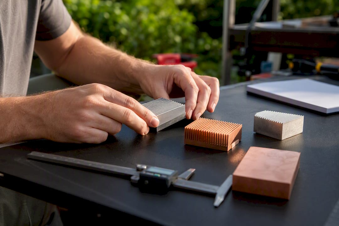
For most air-cooled electronics, extruded 6063 or 6061 aluminum is the pragmatic default. Switch to copper, a copper base with aluminum fins, or a heat pipe hybrid when heat flux climbs past what a wide fin array can handle, or when footprint is too small to spread heat any other way.
The logic behind that verdict comes down to four variables: thermal conductivity, heat flux at the source, manufacturability, and mass. Aluminum runs 160 to 215 W/m·K depending on alloy and temper, extrudes cheaply into complex fin profiles, and weighs about a third of copper. Copper hits 385 to 400 W/m·K, nearly double aluminum’s conductivity, which matters when you need to pull heat away from a small hot spot fast before it ever reaches a fin. But raw conductivity rarely decides the outcome by itself. A well-finned aluminum sink with generous surface area often beats a compact copper block once you account for airflow and fin area at the system level.
Here’s the decision checklist we use before opening a CAD file:
Air-cooled, moderate flux: Start with extruded 6063-T5 aluminum. It’s cheap, light, and easy to tool.
Liquid-cooled: Material still matters, but channel geometry and flow path usually control performance more than base conductivity, so budget simulation time for the fluid side.
High heat-flux, small footprint: Copper base or vapor chamber, often paired with aluminum fins to keep weight down.
Weight-constrained (aerospace, drones, handheld): Aluminum wins on conductivity-per-gram almost every time.
Electrically isolated: Look at anodized aluminum, aluminum nitride, or filled polymers instead of bare metal.
Pro Tip: Before picking a material, run a quick thermal simulation with both aluminum and copper properties swapped in. If the junction temperature barely moves, you’ve just saved yourself a copper premium.
Key Takeaways
Material selection for heat sinks comes down to matching thermal conductivity, heat flux, weight, and manufacturability to the cooling mode, and validating that choice with simulation before committing to hardware.
Point | Details |
Aluminum is the default | 6063 or 6061 aluminum handles most air-cooled designs at low cost and low weight. |
Copper solves spreading problems | Reach for copper or a hybrid design when heat flux is high and footprint is small. |
Fin area often beats conductivity | In air cooling, a well-finned aluminum sink can outperform a smaller copper block. |
Liquid cooling shifts the priority | Flow-path geometry usually matters more than base material conductivity. |
Validate with the Thermalysis Toolkit | Jewlztech’s toolkit lets you compare aluminum, copper, and hybrid materials against the same geometry before building a prototype. |
Table of Contents
When Does Heat Sink Material Selection Actually Matter?
Material choice matters more in some cooling modes than others, and knowing which mode you’re in changes how much engineering time you should spend on the material decision versus the geometry.
In natural convection, airflow is weak and unpredictable, so surface area and fin spacing tend to dominate over conductivity. A cheap aluminum extrusion with tall, widely spaced fins usually outperforms a smaller copper block here, simply because there’s more metal exposed to slow-moving air. Forced air changes the math slightly: higher airflow lets you pack fins closer together, so conductivity starts to matter more at the base where heat concentrates before spreading into the fin array.
Liquid cooling flips the priority entirely. Flow path geometry, channel width, and pump pressure typically drive performance more than the block material itself, which is why flow-path optimization deserves at least as much attention as material choice in cold plate design. Heat pipes and vapor chambers sidestep the conductivity argument altogether by moving heat through phase change rather than solid conduction, often paired with aluminum fin stacks on the condenser side.
Application context tells you where you land on this spectrum:
LED arrays: Often high flux from a small die, favoring copper slugs or heat pipes.
Power IGBTs and SiC modules: High flux plus thermal cycling, where copper or metal-matrix composites earn their cost.
CPUs and GPUs: Copper base spreaders bonded to aluminum or copper fin stacks, sometimes with heat pipes.
Telecom enclosures: Passive aluminum extrusions dominate because of cost and outdoor durability.
EV power electronics: Liquid cold plates where channel design outweighs base material.
The first number you should pull for any new design is heat flux in W/cm². That single figure tells you whether you’re solving a spreading problem or a fin-area problem, and the two call for different materials entirely.
Comparing the Common Heat Sink Materials
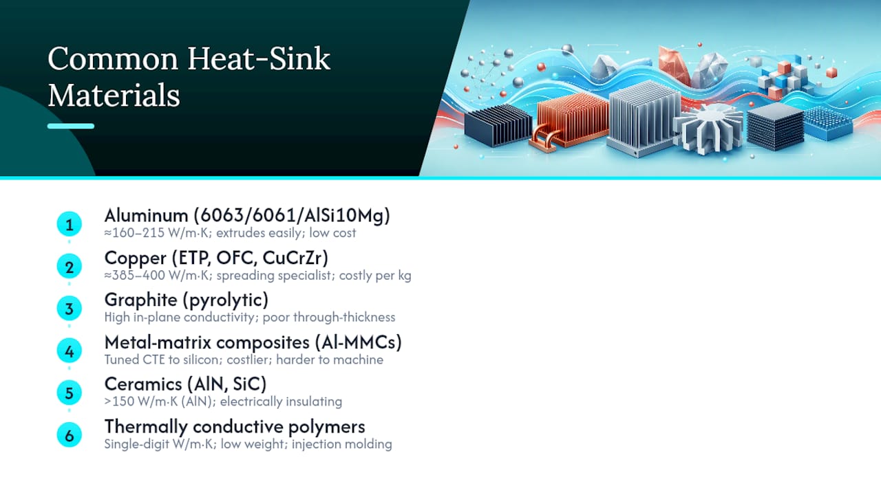
Six material families cover nearly every heat sink you’ll design or spec. Each one earns its place for a different combination of conductivity, weight, cost, and manufacturability.
Aluminum (6063, 6061, 1100/1050, AlSi10Mg) remains the workhorse. 6063-T5 and 6061-T6 conduct heat at roughly 160 to 215 W/m·K, extrude into intricate fin geometries, and cost a fraction of copper per kilogram. 6063 extrudes more easily and takes anodizing well; 6061 machines better and holds tighter tolerances when you need CNC finishing after extrusion. AlSi10Mg shows up in additive manufacturing for complex internal channels you simply can’t extrude or machine.
Copper (C11000/ETP, C10200/OFC, tellurium copper, CuCrZr) is the spreading specialist. Pure electrolytic copper delivers near 385 to 400 W/m·K, making it the right call when a small die needs to dump heat into a wider footprint before a fin array can take over. Tellurium copper machines more easily than pure ETP copper at a small conductivity penalty. CuCrZr adds strength for applications with mechanical loading, at some cost to conductivity.
Graphite and pyrolytic graphite conduct heat anisotropically, meaning conductivity runs high in-plane but poorly through the thickness. That makes graphite sheets excellent heat spreaders in thin, weight-sensitive electronics like laptops and handheld devices, though it’s rarely used as a structural fin material.
Metal-matrix composites (Al-MMCs) blend aluminum with reinforcing particles like silicon carbide to tune the coefficient of thermal expansion closer to silicon or ceramic substrates, reducing stress at solder joints during thermal cycling. They cost more and machine less easily than plain aluminum, but they solve a CTE mismatch problem nothing else on this list addresses cheaply.
Ceramics (aluminum nitride, silicon carbide) conduct surprisingly well for insulators, some AlN grades reaching over 150 W/m·K, while still blocking electrical current. That combination makes them the go-to when a component needs to sit directly on a heat spreader without a dielectric layer.
Thermally conductive polymers and filled plastics trade conductivity (often single digits in W/m·K) for design freedom, low weight, and electrical isolation. They fit low-power consumer electronics where injection molding beats machining on cost at volume.
Pro Tip: Don’t specify copper just because it has higher conductivity on a datasheet. Run the numbers on specific conductivity (conductivity divided by density) if weight matters at all. Aluminum often wins that comparison outright.
How to Choose the Right Heat Sink Material
Work through these six criteria in order, and the right material usually becomes obvious before you reach the bottom of the list.
Set your thermal resistance budget. Know your junction-to-ambient target in °C/W before touching a material chart.
Measure heat flux and source footprint. A 5 W/cm² source on a large die behaves nothing like 50 W/cm² on a 3mm chip.
Confirm the cooling mode. Natural convection, forced air, and liquid cooling each reward different material properties.
Check weight and structural limits. If mass matters, calculate specific conductivity, not just raw W/m·K.
Factor in manufacturability and cost. The cheapest material to buy isn’t always the cheapest to machine into your geometry.
Review electrical isolation and corrosion exposure. Outdoor or humid environments change the finish requirements regardless of base material.
Specific conductivity is worth calculating by hand once so you trust the intuition: divide thermal conductivity by density. Aluminum often comes out ahead of copper on this metric because copper’s conductivity advantage doesn’t fully offset its 3.3x density penalty. Cost-per-watt works similarly, dividing material cost by the wattage the design needs to dissipate at your target temperature rise.
Three quick scenarios show how this plays out:
A 15W LED array on a broad PCB with forced air: aluminum extrusion wins because fin area and airflow dominate, and weight and cost both favor it.
A 40W SiC die on a 10mm square footprint with limited board space: copper spreader bonded to an aluminum fin stack, because the spreading problem outweighs the weight penalty.
A handheld device dissipating 3W with no active airflow and strict weight limits: graphite sheet spreader paired with a thin aluminum frame, since neither copper’s mass nor its cost is justified at this power level.
Notice none of these scenarios pick a material in isolation. Cooling mode, footprint, and weight constraint interact, and the checklist exists to force you through that interaction instead of defaulting to whichever material worked on your last project.
Manufacturing Methods Shape Your Material Options
The fabrication process you plan to use often narrows your material choices before conductivity even enters the conversation.
Extrusion is aluminum’s home turf, particularly 6063, which flows well through dies and produces the tall, thin fin profiles common in passive heat sinks. Die casting handles complex 3D shapes in aluminum at high volume but limits minimum wall thickness compared to extrusion. Skiving, cutting thin fins directly from a solid block, works on both copper and aluminum and produces denser, thinner fin arrays than extrusion allows, at a higher per-part cost. CNC machining suits 6061 aluminum and copper equally well for low-volume or high-precision parts, though copper’s toughness slows cutting speeds and raises tool wear.
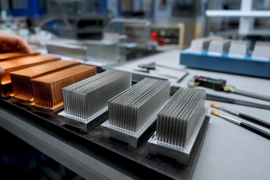
Stamping works for thin aluminum or copper fins in high-volume consumer electronics. Brazing joins copper or aluminum fin stacks to a base plate, often used in liquid cold plates where you need a hermetic, low-resistance joint. Additive manufacturing with AlSi10Mg opens up internal channels and lattice structures no subtractive process can reach, though conductivity and surface finish differ from wrought aluminum and need separate validation.
Process | Typical materials | Best for |
Extrusion | Aluminum 6063 | High-volume passive fins |
Die casting | Aluminum | Complex 3D shapes, moderate volume |
Skiving | Copper, aluminum | Dense, thin fin arrays |
CNC machining | 6061 aluminum, copper | Low-volume, tight tolerances |
Brazing | Copper, aluminum | Cold plates, hermetic joints |
Additive (AM) | AlSi10Mg | Internal channels, lattices |
Rule of thumb: specify 6063 when you’re extruding and cost matters more than tolerance; switch to 6061 the moment you need post-extrusion CNC work or tighter dimensional control. Reach for skived copper fins only when fin density and thermal spreading both need to beat what extruded aluminum can deliver in the same footprint. For a deeper look at how pin fin geometries interact with these processes, the tradeoffs get more specific once you’re comparing fin shapes rather than just materials.
Thermal Interface Materials Change What Base Material You Actually Need
Choosing the base material without accounting for the thermal interface material is a common mistake, because contact resistance and TIM performance often account for more of the total thermal budget than the aluminum-versus-copper decision itself.
Thermal grease and paste offer the lowest bulk resistance among reworkable options but require careful application thickness. Phase-change materials behave like solid pads at room temperature and liquefy at operating temperature, giving more consistent wetting than grease. Thermal pads are easiest to apply in production but add more thermal resistance than grease or solder. Solder and brazed joints deliver the lowest resistance of all, permanently bonding the sink to the source, common in high-reliability power electronics.
Attachment method matters just as much as the TIM itself:
Mechanical fastening (screws, clips): Reworkable but sensitive to pressure and flatness.
Solder or braze: Lowest resistance, permanent, requires compatible metallurgy.
Thermal epoxy: Good for lightweight assemblies where mechanical fasteners aren’t practical.
Press-fit: Fast for high-volume assembly, less consistent contact pressure over time.
Pro Tip: If you’re bonding a copper base to an aluminum fin stack, plate the contact surface with nickel first. Direct copper-to-aluminum contact in humid environments sets up galvanic corrosion that degrades thermal performance over time.
Surface Finishes and Coatings Worth Specifying
Anodizing aluminum increases surface emissivity, which helps radiative heat transfer in natural convection designs, and it adds a thin electrically insulating layer that’s useful near live conductors. Nickel plating on copper prevents oxidation and improves solderability, while also acting as a barrier layer when copper contacts aluminum. Electroplating and passivation both extend service life in humid or corrosive environments without meaningfully hurting conductivity at typical coating thicknesses.
A few practical rules:
Plate copper with nickel whenever it touches aluminum directly, to block galvanic corrosion.
Anodize aluminum heat sinks going into outdoor or marine environments.
Machine or lap contact surfaces flat before applying any TIM; a coating can’t compensate for a warped base.
Expect anodized layers to age gracefully, but watch for coating degradation on parts exposed to UV and thermal cycling over multiple years.
Fin Efficiency, Spreading Resistance, and Two Worked Examples
Two formulas do most of the heavy lifting in early-stage material decisions. Fin efficiency tells you how much of a fin’s surface area actually contributes to heat transfer, and it drops as fins get thinner, taller, or made from lower-conductivity material. Spreading resistance estimates the extra thermal resistance created when heat enters a base plate from a smaller source footprint than the plate itself, and it’s where copper’s conductivity advantage shows up most clearly.
The combined thermal resistance budget adds up as: source-to-case resistance, plus spreading resistance in the base, plus fin/convective resistance to ambient. Material choice mainly affects the middle two terms.
Two scenarios illustrate when each term dominates:
Broad, low-flux source (5 W/cm² over a 40mm square die) with forced air. Spreading resistance is minor because the source already covers most of the base. Convective resistance from fin area dominates the budget, so aluminum with more fin surface area wins over a smaller copper block every time.
Small, high-flux hot spot (60 W/cm² over an 8mm die) on the same base footprint. Spreading resistance now dominates because heat has to travel laterally through the base before reaching the fins. Copper’s conductivity advantage, or a vapor chamber, meaningfully cuts total resistance here in a way aluminum can’t match at the same base thickness.
As a quick field check, engineering discussions on material tradeoffs consistently flag heat flux above roughly 20 to 30 W/cm² as the point where spreading starts to matter more than fin area, though the exact threshold shifts with base thickness and footprint ratio. Below that, spend your engineering effort on fin geometry and airflow, not material upgrades. For the underlying math, fin efficiency formulas and worked examples walk through the calculation in more detail than fits here.
A Simulation Workflow to Validate Your Material Choice
Don’t guess between aluminum and copper. Model it. A compact simulation workflow settles the question faster than ordering two prototypes and testing both.
Define your performance target. Junction temperature limit, ambient temperature, and available airflow or flow rate.
Build a simplified thermal model. Base plate, fin array, and heat source footprint, without unnecessary geometric detail.
Vary the base material and geometry. Swap aluminum and copper properties, including alloy and temper, while holding geometry constant first.
Run steady-state and transient simulations. Transient runs matter for pulsed loads like power electronics switching.
Validate with a prototype. Measure junction temperature and case temperature against simulation predictions.
Before trusting the output, check a short list: material property fidelity (alloy and temper, not just “aluminum”), contact resistance and TIM modeling, correct airflow boundary conditions, and fine enough meshing on thin fins to capture the temperature gradient accurately. Required outputs should include junction temperature, total thermal resistance, mass, and pressure drop if a fan is involved. A detailed heat transfer model covering these formulas gives you the math to sanity-check simulation results by hand before you commit to a design.
On the bench, expect prototype measurements to land within a few degrees of simulation if your material properties and boundary conditions were accurate. Bigger gaps usually point to unmodeled contact resistance, not a wrong material choice.
What I’ve Learned Choosing Heat Sink Materials on Real Projects
Every project I’ve worked through starts with the same question: what’s the heat flux, and how much of the footprint does the source actually cover? That single number rules out half the material list before cost or weight ever enters the conversation.
Three habits save the most time. First, measure heat flux before opening a materials chart, not after. Second, specify alloy and temper explicitly. “Aluminum” isn’t a material spec, and 6061 versus 6063 changes both conductivity and what your machine shop can do with it. Third, consider a hybrid or heat pipe before jumping straight to solid copper.
None of this replaces validation. Run the simulation, then build the prototype.
Speed Up Material Comparisons With the Thermalysis Toolkit
Running the aluminum-versus-copper comparison by hand for every design gets old fast, especially once you’re juggling alloy tempers, TIM resistance, and transient loads on top of it. The Thermalysis Toolkit handles that comparison inside one spreadsheet, with a built-in material property database covering common alloys and grades so you’re not hunting datasheets mid-design.

The toolkit runs conduction, convection, and radiation modules together, lets you swap material properties by temperature, and produces exportable reports you can drop straight into a design review. Because it’s built for iteration, you can compare aluminum, copper, and hybrid configurations against the same geometry in minutes rather than rebuilding a model each time. If you want to see how it handles a real design before committing, check out the Thermalysis Toolkit product page and start with a trial run on your current heat sink comparison.
Frequently Asked Questions
What is the best material for heat sinks in most applications? Extruded aluminum, typically 6063 or 6061, handles the majority of air-cooled electronics well because it balances thermal conductivity, low weight, and low manufacturing cost.
Is copper always better than aluminum for heat sinks? No. Copper conducts heat faster, but aluminum frequently wins at the system level in air-cooled designs because it supports more fin area for the same weight and cost.
When should I choose a hybrid heat sink material? Choose a copper base with aluminum fins, or a heat pipe paired with aluminum fins, when your heat source has high flux over a small footprint but the overall design still needs to stay light and affordable.
Do ceramics work as heat sink materials? Aluminum nitride and silicon carbide conduct heat well while remaining electrically insulating, making them useful when a component must sit directly on a spreader without a separate dielectric layer.
How much does thermal interface material affect material choice? Significantly. Contact resistance and TIM performance often account for more of the total thermal budget than the difference between aluminum and copper, so model the TIM before finalizing the base material.
Sources
Pull alloy datasheets for 6063 and 6061 aluminum and C11000 copper directly from supplier property tables before finalizing a design, and consult the comparative FAHP-TOPSIS material evaluation for a rigorous multi-criteria ranking methodology. Check any datasheet or standard your alloy supplier provides for exact conductivity and temper data, and feed those verified values into your simulation model rather than relying on generic textbook figures.
Recommended
Comments