
Simulation First LED Thermal Management for Engineers: LM-85

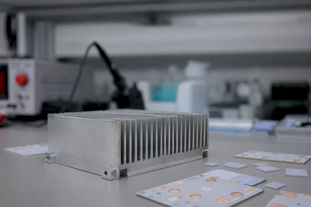
Effective LED thermal management comes down to one job: keep junction temperature (Tj) as low and stable as possible by minimizing junction-to-ambient thermal resistance (RthJA). That means pairing a low-resistance TIM with a well-matched MCPCB, a heat sink sized for the actual power density, and simulation that validates the stack before you cut metal. Datasheet Tj limits, checked against LM-85 and LM-80 test data, are the ceiling you design under, not the target you hope to avoid.
TL;DR:
Maintaining low junction-to-ambient resistance is essential, with a focus on proper TIM application, appropriate heat sink size, and validated thermal stacking in simulations.
Accurate measurement of junction temperature relies on placing thermocouples near the die, using proper RthJS values, and following standardized testing conditions like LM-85.
Effective passive cooling depends heavily on TIM bond-line thickness, fin spacing, surface finish, and material choice, with simulation validation key before finalizing designs.
Active cooling solutions such as thermoelectric modules or liquid cooling become necessary only when passive options cannot handle high power densities within spatial constraints.
Simulation-driven design, especially coupling CFD with thermal estimation, enables reliable validation and material savings without extensive physical prototyping.
Table of Contents
What Is LED Thermal Management and Why Junction Temperature Drives Everything
How to Measure and Specify Junction Temperature the Right Way
Passive Cooling Components: TIMs, MCPCBs, and Heat Sinks Explained
When Do You Need Active Cooling Instead of Passive Heat Sinks?
Simulation Workflows That Validate Thermal Designs Before Production
LED Thermal Design Checklist: What to Verify Before You Commit to Tooling
Get Simulation-Validated Thermal Designs Without Building a Physical Prototype for Every Iteration
What Is LED Thermal Management and Why Junction Temperature Drives Everything
LED thermal management is the discipline of controlling how heat generated at the semiconductor junction moves out to ambient air, because that path determines both light output and service life. An LED converts roughly 70 to 85 percent of input power into heat rather than photons, mostly through non-radiative recombination inside the die and, in phosphor-converted white LEDs, additional heating in the phosphor layer itself as it absorbs and re-emits shifted wavelengths.
That heat has nowhere to go but through the package. Engineers model the path as a series of thermal resistances, each one a bottleneck the heat has to cross:
RthJC (junction to case): resistance from the die to the package’s thermal pad, usually the smallest number but the hardest to shrink further once the package is chosen.
RthJB (junction to board): resistance from die to the PCB, heavily dependent on die attach and package construction.
RthJA (junction to ambient): the full path from die to surrounding air, the number that actually determines Tj in operation.
Stack those resistances against the LED’s forward power and you get a temperature rise. The consequences of letting that number run high are not subtle. Luminous flux output declines significantly with rising junction temperature, for example around 20 percent drop for a 50°C increase, a relationship documented in the measurement work behind IES/ANSI LM-85. Push Tj even higher and you’re not just losing lumens. You’re accelerating phosphor degradation, encapsulant yellowing, and solder joint fatigue, all of which compound lumen depreciation faster than the LM-80 lumen maintenance curve would predict at a lower operating temperature. A fixture spec’d for L70 at 60,000 hours can quietly become an L70-at-20,000-hours fixture if the thermal path was under-designed from day one.
How to Measure and Specify Junction Temperature the Right Way
You can’t manage what you don’t measure, and Tj is not directly measurable in a finished fixture. Engineers estimate it from a more accessible reference point, usually the solder point or board temperature near the LED, using a straightforward relationship:
Tj = Ts + PHeat × RthJS
Here Ts is the measured solder or board temperature, PHeat is the actual heat-generating power (not total electrical input power, since some fraction leaves as light), and RthJS is the junction-to-solder-point thermal resistance from the manufacturer’s datasheet. Get any one of those three wrong and the estimate drifts, so measurement discipline matters as much as the math.
Pull RthJS from the datasheet, not RthJC. Many manufacturers publish junction-to-solder-point resistance separately because it reflects the actual measurement point used in production testing.
Follow LM-85 test conditions for any comparative data. ANSI/IES LM-85 standardizes how manufacturers characterize thermal and electrical performance, so specs from different vendors are only comparable when tested under it.
Cross-reference LM-80 and LM-79 for lumen maintenance and photometric claims. LM-80 governs long-term lumen and color maintenance testing; LM-79 governs the photometric measurement methodology. Neither one measures Tj directly, but both assume a known thermal operating point.
Place thermocouples where OSRAM’s AN085 application note recommends, typically in a solder inspection cavity or at a designated pad near the die rather than on an arbitrary board location. This single choice is the most common source of measurement error in field reports.
Correlate thermocouple readings with simulation probe points. If your CFD model samples a different node than your physical thermocouple, the two numbers will disagree even when the hardware is fine.
The most frequent pitfall isn’t equipment error. It’s measuring board temperature far from the die and assuming it equals Ts, or using RthJC where RthJS was called for. Both mistakes understate real Tj by a meaningful margin, and a fixture that looks safe on paper runs hot in the field.
Passive Cooling Components: TIMs, MCPCBs, and Heat Sinks Explained
Passive thermal solutions handle the overwhelming majority of LED cooling, and for good reason: no moving parts, no power draw, no maintenance schedule. But “passive” doesn’t mean “simple.” Every interface in the stack is a resistance you either control or lose to.
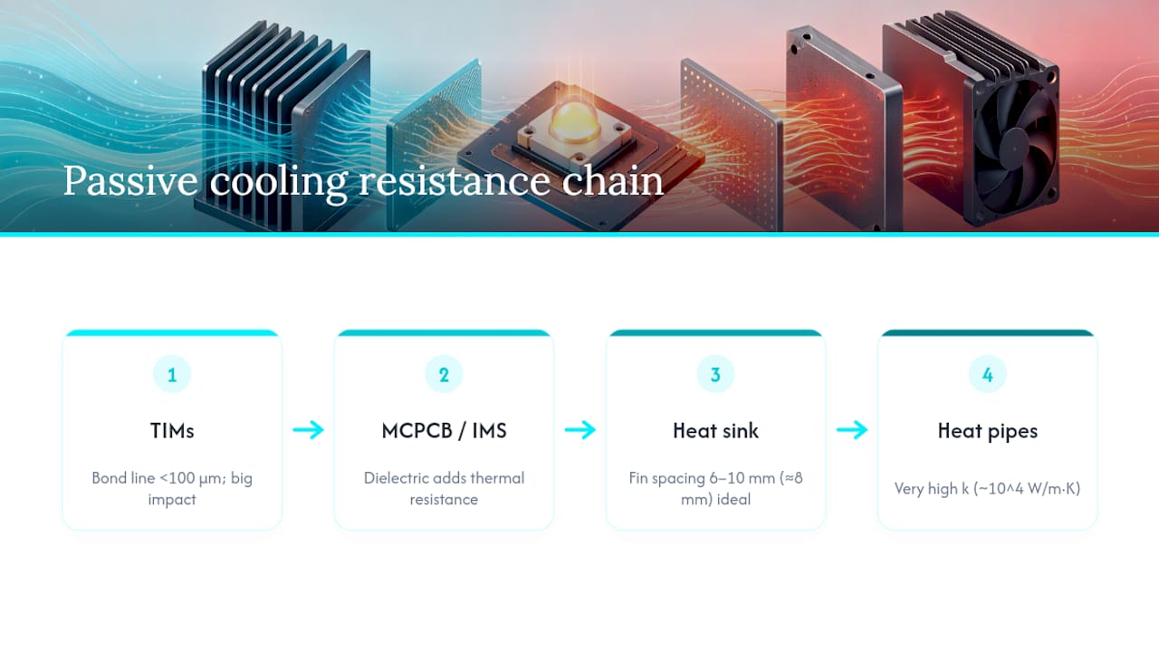
Thermal interface materials (TIMs) are the most underrated variable in the entire chain. A gap-filling pad or thermal grease looks identical to a rival product on a datasheet until you check bond-line thickness. Keep bond lines under 100 microns wherever possible. Contact resistance rises sharply once the interface gets thicker or the material can’t wet the surfaces properly, and that resistance sits directly in series with everything downstream. For LED modules with higher power, high-conductivity thermal interface materials that achieve low interface resistance are recommended. Below that power level, well-applied thermal grease or a quality pad usually suffices.
MCPCBs and insulated metal substrates (IMS) move heat laterally from the LED footprint before it ever reaches the heat sink. An aluminum-clad MCPCB with a thin dielectric layer is the standard choice for mid-power arrays, but that dielectric is itself a thermal bottleneck. Thinner dielectric layers cut resistance but reduce dielectric strength and mechanical robustness, so high-voltage or safety-isolated designs sometimes need a thicker layer that costs you thermal performance elsewhere in the stack. Copper-core boards perform better thermally than aluminum but add cost and weight, which matters in large-area fixtures like linear high-bays.
Heat sinks for natural convection follow fin-spacing rules that are easy to get wrong by eyeballing it. Practical natural-convection designs typically optimize fin spacing around 6 to 10 millimeters, with roughly 8 millimeters as a reliable starting point for most residential and commercial fixture geometries. Space fins too tightly and you choke natural airflow between them; space them too wide and you waste surface area. Surface emissivity matters more than most engineers give it credit for. An anodized black finish radiates substantially more heat than bare aluminum, often enough to shave several degrees off Tj at zero material cost. Jewlztech’s heat sink design guide walks through the fin geometry math in more detail, and choosing between aluminum, copper, and composite materials changes both the thermal and weight budget.
Heat pipes and vapor chambers earn their place when you need to move heat somewhere the LED array can’t reach directly, or when you need to isothermalize a heat sink that would otherwise have hot spots. Their effective thermal conductivity ranges from very high values on the order of tens of thousands of W/m·K, far exceeding solid metals, an order of magnitude or more beyond solid copper, which is why they show up in high-bay and stadium fixtures where the sink has to sit remote from the emitter. They also let designers cut heat-sink mass, since the vapor chamber spreads heat across a larger fin area than direct conduction would achieve on its own.

At the package level, flip-chip LEDs reduce internal thermal resistance by eliminating wire bonds and putting the die closer to the substrate, shrinking RthJC before the heat ever reaches your TIM. If you’re specifying LEDs for a thermally demanding application, checking package architecture matters as much as picking the right heat sink.
Pro Tip: Don’t spend your engineering hours re-optimizing heat-sink fin count before you’ve verified TIM bond-line thickness under real assembly pressure. A 50-micron gap you didn’t account for can erase more thermal margin than a redesigned fin array will ever recover.
When Do You Need Active Cooling Instead of Passive Heat Sinks?
Active cooling earns its complexity only when passive designs physically run out of room or surface area to shed the required heat load. That threshold usually shows up around high power densities in confined enclosures, think stage lighting, automotive headlamp modules, or medical illumination where the fixture footprint is fixed and non-negotiable.
Thermoelectric (TE) modules use the Peltier effect to actively pump heat from a cold side to a hot side, and they can pull Tj below what any passive design achieves in the same footprint. The catch is real: TE modules consume power themselves, adding to the total heat load they need to reject, and they introduce a new failure mode at the TE-to-heat-sink interface that needs its own TIM strategy. They make sense in compact, high-value optical systems where a few degrees of Tj reduction meaningfully extends service life, but rarely in general-purpose fixtures where the power penalty and cost don’t pencil out.
Liquid cooling loops move heat via a pumped coolant through a cold plate mounted near the LED array, then reject it at a remote radiator. This scales to power densities passive and TE solutions can’t touch, but it introduces pump reliability as a new failure point, coolant leak risk, and a maintenance schedule most lighting applications were never designed to support.
Deciding between the two, or sticking with passive, comes down to a few practical filters:
If passive fin area physically doesn’t fit the enclosure at the required power, active cooling is justified.
If the application tolerates noise and periodic maintenance, liquid cooling opens up higher power ceilings than TE modules.
If cost and reliability matter more than squeezing out the last few degrees, passive with a better TIM and heat-sink geometry usually beats active cooling on total lifecycle value.
Jewlztech’s decision guide for active versus passive cooling breaks these thresholds down further if you’re on the fence for a specific design.
Simulation Workflows That Validate Thermal Designs Before Production
Simulation earns its place in the LED thermal workflow because prototype iteration is slow and expensive, and because the interactions between TIM resistance, board conduction, and heat-sink convection are too coupled to reason through by hand.
Build the geometry and assign real material properties. Use actual TIM conductivity and bond-line thickness, not catalog nominal values, since installed bond lines routinely run thicker than the datasheet number.
Define heat sources from actual electrical operating points, not rated maximum power, unless you’re specifically validating a worst-case scenario.
Run steady-state first, then transient. Steady-state gives you the equilibrium Tj; transient reveals thermal cycling behavior that matters for solder joint fatigue in dimming or pulsed applications.
Couple electro-thermal effects where forward voltage and efficiency shift meaningfully with temperature, since LED electrical behavior isn’t thermally independent.
Correlate simulated Ts and Tj against physical thermocouple measurements at the same probe locations used in your OSRAM AN085 measurement setup, and iterate the model until the gap closes to a few degrees.
Full CFD captures airflow and convection detail that reduced-order thermal-resistance models simply can’t, but it costs more compute time. Reduced-order models are the right tool for quick sensitivity studies, sweeping TIM thickness or fin spacing across a dozen configurations before committing to a full CFD run on the top candidates.
Simulation-led optimization can meaningfully cut package temperature while reducing material use compared to conventional lattice-fin heat-sink designs. A 2018 study on topology-optimized heat-sink geometry demonstrated this directly, showing that algorithmically generated fin structures outperformed standard designs on a temperature-per-gram basis. A 2026 review of LED thermal management reinforces that electro-thermal modeling and simulation-validated design are becoming standard practice for multi-objective gains in both cooling efficiency and weight.
The practical upshot: if you’re still hand-sketching fin arrays and building a physical prototype to test them, you’re leaving performance and material savings on the table that topology optimization tools already capture reliably. Jewlztech’s conjugate heat transfer simulation guide covers the coupled solid-fluid setup this kind of validation requires.
LED Thermal Design Checklist: What to Verify Before You Commit to Tooling
Before a design goes to tooling, run it against a short list that catches the mistakes that show up in field returns, not in bench testing.
Confirm datasheet Tj limit and derive your target operating Tj with margin, not at the limit.
Verify RthJS from the datasheet matches the measurement point you’ll actually use for validation.
Check TIM bond-line thickness under real assembly clamping force, not nominal spec.
Confirm MCPCB dielectric thickness against both thermal and electrical isolation requirements.
Validate fin spacing and surface finish against the natural-convection airflow the enclosure actually allows.
Run steady-state and transient simulation, then correlate against thermocouple data before sign-off.
Checklist Item | Acceptance Margin | Red Flag |
Operating Tj vs. datasheet limit | 20°C margin below rated max | Design runs within 5°C of limit at nominal power |
TIM bond-line thickness | Under 100 µm as assembled | Measured thickness exceeds spec after clamping |
Simulation vs. measured Tj correlation | Within a few degrees Celsius | Gap exceeds 10°C with no explanation |
Fin spacing for natural convection | 6 to 10 mm | Spacing under 6 mm or over 10 mm with no CFD check |
A design review that skips the simulation correlation step is the one most likely to surface a field failure six months after launch.
How Jewlztech Approaches LED Thermal Design Problems
Joel leads thermal content and simulation methodology at Jewlztech, where the day-to-day work centers on helping engineers validate thermal designs before they commit to tooling costs. The recommended workflow follows a consistent sequence: measure real operating temperatures at the correct probe location, build a simulation model calibrated against that measurement, optimize geometry and material selection against the model, then validate the optimized design with a second measurement pass.
A few things worth flagging from that process. TIM bond-line control catches more field-failure root causes than any other single variable, so it deserves disproportionate attention during design review, not just at final assembly sign-off. Thermocouple placement following the AN085 methodology consistently produces better simulation correlation than surface-mounted infrared readings on small die packages. Related reading on PCB thermal analysis workflow and Jewlztech’s thermal analysis software covers the tooling side of this workflow in more depth.
What Actually Moves the Needle on LED Reliability
Most thermal design advice for LEDs overweights heat-sink mass and underweights interface resistance, and that priority is backwards. A bigger heat sink is the easy fix everyone reaches for, but a 50-micron TIM gap can undo more thermal margin than doubling your fin surface area recovers. The conventional wisdom treats the heat sink as the star of the show. It’s actually the last link in a chain, and chains break at their weakest point, not their strongest one.
The bigger shift worth naming: simulation-first design used to be a luxury reserved for high-volume production runs where the tooling cost justified the modeling effort. That math has changed. Topology-optimized geometries and electro-thermal coupling are now accessible enough that skipping simulation on a mid-volume fixture is a choice to leave material savings and reliability margin on the table, not a cost-saving shortcut.
If you take one thing from this, prioritize the measurement-simulation correlation loop before you touch fin geometry. Get your Tj estimate right, calibrate your model against it, and the optimization step becomes straightforward. Skip that calibration and every subsequent design decision is built on a number you can’t trust.
— Joel
Get Simulation-Validated Thermal Designs Without Building a Physical Prototype for Every Iteration
Prototyping every TIM, heat-sink geometry, and fin-spacing variant on the bench costs weeks and material budget that simulation can replace in an afternoon. Jewlztech’s engineering toolkit gives you conduction, convection, and radiation calculations with a built-in material property database, so you can screen TIM and heat-sink candidates before committing to a physical build.

For coupled solid-fluid problems, like verifying how a TIM choice actually performs under real airflow rather than an idealized boundary condition, the CFD simulation software handles conjugate heat transfer analysis directly. And if your design goal is squeezing more cooling performance out of less material, the heat exchanger optimization software applies the same topology-optimization logic covered in this article’s simulation section.
A practical starting project: run a conjugate heat transfer verification on your current TIM selection before your next design freeze. Start with the engineering toolkit and see whether your assumed bond-line thickness holds up under simulated clamping conditions.
Where to Go Deeper on LED Thermal Standards and Research
For engineers who want the primary sources behind these design rules rather than a secondhand summary:
ANSI/IES LM-85: the reference standard for measuring LED thermal and electrical characteristics under controlled conditions.
LM-80/LM-79: the companion standards governing lumen maintenance testing and photometric measurement methodology, respectively.
Lumileds WP31: practical heat-sink design guidance grounded in real fixture geometries.
OSRAM AN085: the application note behind correct thermocouple placement for Tj estimation.
2026 ScienceDirect review: current synthesis of thermal-management mechanisms and simulation-driven optimization trends.
blog.tempered.to on GPU cooling: a useful cross-industry reference on fin geometry and passive-cooling heuristics that transfer directly to LED fixture design.
Sources
Recommended
Comments