
Engineers: Insulated Pipe Heat Loss, 86% Cut Using 1.5 in Fiberglass

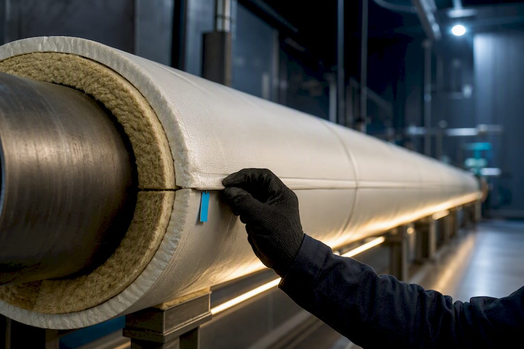
Insulation almost always cuts heat loss per unit length substantially, but only above a threshold called the critical radius. A bare 2-inch steel pipe carrying 300°F fluid in 70°F air loses a significant amount of heat per foot; adding 1.5 inches of fiberglass insulation significantly reduces heat loss. The controlling variables are ΔT, insulation conductivity (k), thickness, and the outside film coefficient (h).
TL;DR:
Insulation only reduces heat loss when its outer radius exceeds the critical radius, which depends on the insulation’s conductivity and the outside convective coefficient.
Adding insulation below the critical radius can increase heat loss due to increased surface area for convection, especially with higher airflow or forced convection.
Hand calculations work well for simple, steady-state pipe insulation but break down with transient loads, complex fittings, or cryogenic systems, requiring advanced simulation tools.
Proper field measurements of convection coefficients and consistent unit use are crucial for accurate heat loss estimates and effective insulation design.
Safety requirements often demand thicker insulation than what economic models suggest, so always choose the greater of the two when sizing pipe insulation.
Table of Contents
Insulated Pipe Heat Loss Calculator: What the Numbers Mean
A heat loss calculator is only as good as its inputs, and most errors trace back to one of six values: pipe outer diameter, insulation thickness, insulation k value, fluid or surface temperature, ambient temperature, and the assumed convective coefficient h.
The outputs worth trusting are linear heat loss (BTU/hr per foot, or watts per meter), estimated outer jacket surface temperature, annualized energy cost when you multiply by run hours and fuel price, and simple payback against the insulation’s installed cost. Most calculators default to a still-air h and a steady-state assumption, meaning:
They ignore startup transients and cyclical loads, so intermittent steam lines will show more real-world loss than the model predicts.
They assume constant k, when real insulation conductivity rises with mean temperature, sometimes 15 to 30% higher at 400°F than at 100°F.
They treat the pipe run as uniform, missing joints, supports, and valve bodies that leak heat disproportionately.
Unit conversion trips people up more than the math does. One BTU/hr·ft equals roughly 0.961 W/m, and mixing SI and Imperial mid-calculation is the single most common source of a wrong answer in student submissions.
The Math Behind Cylindrical Heat Loss
Heat loss through an insulated pipe combines two resistances in series: conduction through the cylindrical insulation shell, then convection off the outer surface to ambient air. For a pipe with inner insulation radius r1 (essentially the pipe OD) and outer insulation radius r2, the combined heat-rate formula is:
Q/L = 2π·ΔT / [ (ln(r2/r1) / k) + (1 / (r2·h)) ]
where ΔT is the temperature difference between the pipe surface and ambient air, k is insulation thermal conductivity, and h is the outside convective coefficient. The first term in the denominator is conductive resistance through the insulation; the second is convective resistance at the outer jacket.
Differentiate total resistance with respect to r2 and set it to zero, and you get the critical radius:
r_cr = k / h
Below r_cr, adding insulation can increase the convective surface area faster than it adds conductive resistance, leading to a rise in total heat loss before it eventually falls. Above r_cr, every added layer reduces heat loss, which is the regime almost all real piping operates in.
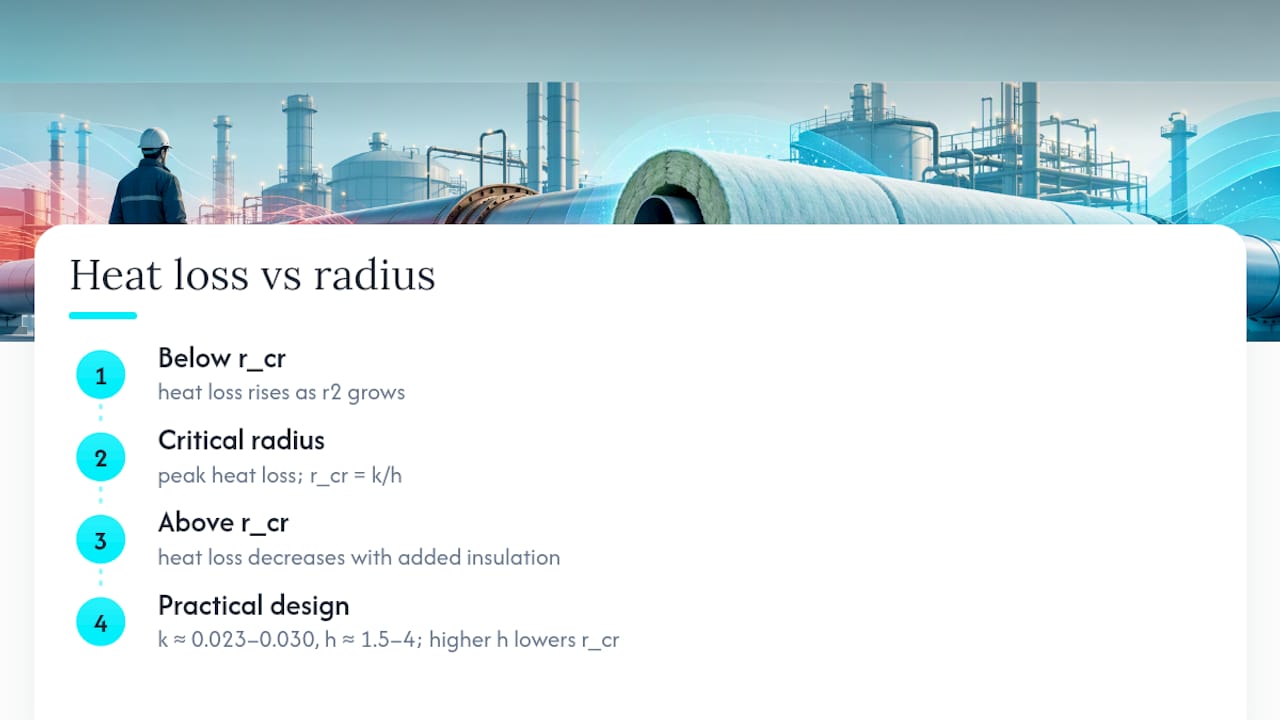
Rearranging for design work, you solve for required r2 given a target Q/L, or back into thickness (r2 minus r1). Plug in k around 0.023 to 0.030 BTU/hr·ft·°F for mineral wool or fiberglass, and h around 1.5 to 4 BTU/hr·ft²·°F for still to lightly moving air, and you have workable starting numbers for a hand check before running a full model.
Critical Radius of Insulation: When More Material Backfires
The critical radius r_cr = k/h tells you the insulation outer radius below which additional thickness increases heat loss instead of reducing it. It sounds counterintuitive until you picture why: thin insulation on a small conductor adds surface area for convection faster than it adds resistance through the material, so the pipe sheds heat into a bigger “radiator” before the insulating effect catches up.
The magnitude of h decides how much this matters:
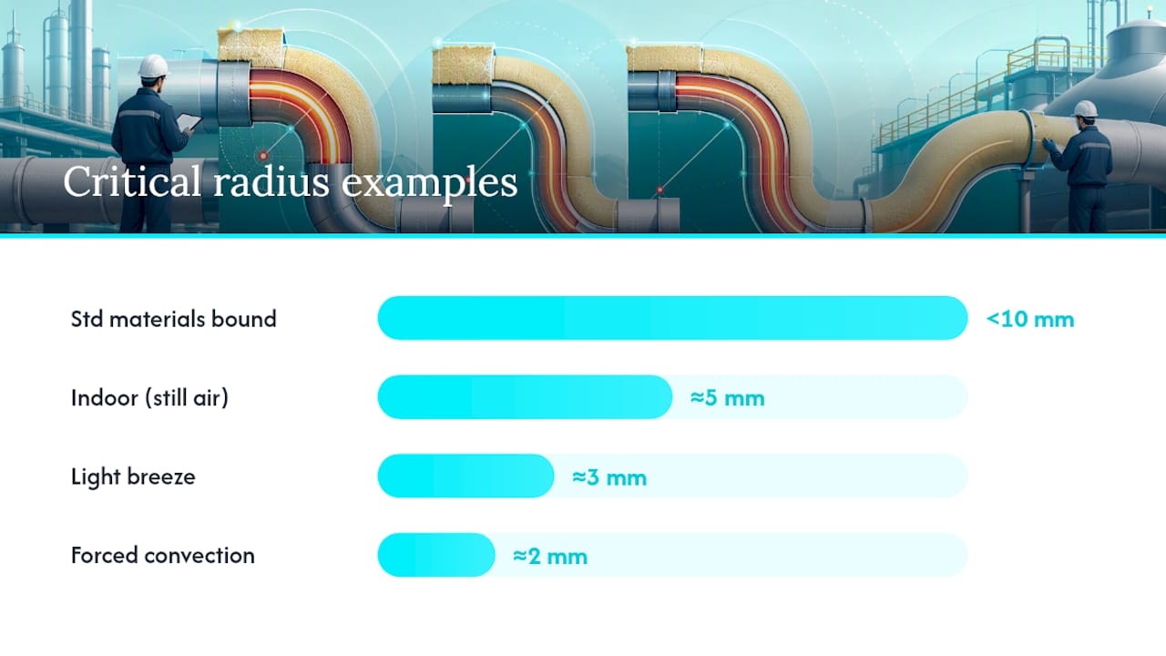
Still indoor air typically has a convective coefficient h that leads to small critical radius values on the order of millimeters for typical insulation k values.
Light outdoor breeze increases the convective coefficient h, pushing the critical radius lower, often to a few millimeters or less.
Forced convection (fans, ducted airflow): h can exceed 15 to 20 BTU/hr·ft²·°F, shrinking r_cr to a couple of millimeters or less.
On most piping this is a non-issue. Analysis from Simon Fraser University’s heat transfer coursework confirms r_cr for standard insulating materials is usually under 10 mm, well inside the outer radius of anything larger than a small-gauge wire or thermocouple lead. The concern is real for electrical conductors and thin capillary tubing, not for 2 inch process pipe.
Wind and forced flow raise h, which lowers r_cr and makes the critical-radius trap even less likely on exposed outdoor piping. The exception worth flagging: cryogenic lines and small-diameter instrumentation tubing, where even a thin jacket can sit near r_cr, and getting it wrong measurably worsens boil-off or condensation control.
Choosing Pipe Insulation Thickness: Economic vs Safety Limits
Two separate criteria set minimum insulation thickness, and they don’t always agree. The energy-driven approach, formalized in ASTM C680’s economic thickness methodology, balances installed insulation cost against the present value of energy saved over the system’s life. Industry practice generally targets 30 to 75 BTU/hr·ft for process steam lines, with the Department of Energy favoring 50 BTU/hr·ft or tighter as a practical ceiling for continuously operating steam piping.
The safety-driven approach is simpler and non-negotiable: OSHA’s guidance holds that surface temperatures above 140°F risk contact burns, so insulation must be thick enough to bring the jacket below that line regardless of what the economic model says. On small-diameter, high-temperature lines, the safety criterion frequently calls for more thickness than the economic optimum. On large-diameter lines, it’s usually the reverse.
Practical selection rules that hold up in the field:
Pick whichever thickness is larger between the economic-optimum result and the OSHA 140°F requirement; never split the difference.
Lower-k materials, phenolic foam versus standard fiberglass, for instance, can cut required thickness roughly in half for the same performance, which matters when clearance is tight.
Manufacturer datasheets, like Owens Corning’s fiberglass pipe insulation specifications, list temperature-dependent k values you should use instead of a single “typical” number for anything running above 300°F.
Worked Example: Bare Pipe vs Insulated Pipe Heat Loss
Take a 2 inch NPS steel pipe (2.375 inch OD, so r1 = 0.099 ft), carrying fluid that keeps the pipe surface at 300°F, in 70°F ambient air with h ≈ 2.0 BTU/hr·ft²·°F.
Bare pipe loss: Q/L = h · (2π·r1) · ΔT = 2.0 × (2π × 0.099) × 230 ≈ 286 BTU/hr·ft, well above any reasonable target.
Add 1.5 inches of fiberglass (k = 0.025 BTU/hr·ft·°F), so r2 = 0.099 + 0.125 = 0.224 ft.
Apply the combined formula: conductive term = ln(0.224/0.099)/0.025 ≈ 32.7; convective term = 1/(0.224 × 2.0) ≈ 2.23. Total resistance ≈ 34.9.
Insulated Q/L = 2π × 230 / 34.9 ≈ 41.4 BTU/hr·ft, an 86% reduction from bare pipe.
Check surface temperature: the outer jacket runs close to ambient plus a small delta, typically 90 to 110°F here, comfortably under the OSHA 140°F limit.
Each added inch delivers diminishing returns, which is exactly what the economic-thickness math is built to quantify.
Field Tips for Getting Insulated Pipe Heat Loss Right
Unit mismatches cause more bad answers than bad formulas. Confirm every input is in one consistent system before you touch a calculator, and re-derive k at your actual mean temperature rather than borrowing a room-temperature value from a spec sheet.
Don’t assume still-air h indoors near vents, fans, or open bay doors; measured h there often runs two to three times the still-air assumption.
Outer-surface thermography is the fastest field check: a hot spot on a jacket usually means a compressed, wet, or missing insulation section, not a calculation error.
Estimate h from local wind speed or duct velocity using forced-convection correlations rather than a generic textbook constant when the pipe run sits in moving air.
Jacketing matters as much as the insulation itself. UV-degraded or torn cladding lets moisture in, and wet insulation can lose most of its rated R-value.
Pro Tip: Walk any insulated run with an infrared camera after the first heating season. Cold, wet insulation shows up as a warm streak on the jacket long before anyone notices a utility bill creep.
Hand Calculations vs Simulation: Knowing the Limit
Hand calculations and simple calculators work well for straight runs, steady-state loads, and single-material insulation. They break down for transient startup/shutdown cycles, complex fittings and thermal bridges, coupled radiation at high temperature, or cryogenic boil-off where phase change dominates.
Jewlztech’s thermal-analysis toolkit handles multi-mode conduction, convection, and radiation with variable material properties, while the CFD simulation tools resolve geometry a cylindrical formula can’t. Run the hand calculation first; escalate when the answer needs to survive an audit.
An Engineer’s Take on Insulation Trade-offs
Safety wins every argument with economics. If OSHA’s 140°F limit and the economic-thickness result disagree, spec the thicker one and move on. A calculator earns its keep on straight, steady-state runs; the moment fittings, transients, or cryogenics enter the picture, trust a simulation over a spreadsheet.
— Joel
Try Jewlztech’s Simulation Toolkit for Complex Runs
The worked example above covers a straight pipe under steady conditions, which is exactly where hand calculations stop being enough once your system has bends, transient loads, or coupled radiation. Jewlztech built its engineering toolkit for that gap: physics-based thermal simulation with a built-in property database, so you’re not manually chasing temperature-dependent k values across a spreadsheet. For heat-exchanger circuits feeding your piping network, the heat exchanger optimization software models coupled thermal behavior a single cylindrical formula can’t touch. Download the free tools, run your actual geometry, and see where the hand calculation and the simulation start to diverge.
Sources
For deeper verification, the critical radius calculator at HVAC-eng lets you check r_cr against your own k and h values. TWC Industrial’s thickness calculator walks through ASTM C680 economic-thickness logic in more detail, and Pipelagging covers prescriptive BS5422 tables for readers working outside US codes.
Recommended
Comments