
Add 8.7 psi: Design Pressure vs. MAWP for U.S. Engineers


Design pressure is the number you choose. MAWP is the number the code hands back to you after checking every component against reality. Design pressure feeds into the calculation as an input alongside design temperature; MAWP is the output, the ceiling stamped on the nameplate once material thickness, corrosion allowance, and joint efficiency have all had their say. In most designs MAWP ends up equal to or higher than design pressure, but treating the two as interchangeable without doing the math is where mistakes creep in.
TL;DR:
Calculated MAWP often exceeds the initial design pressure because standard material thicknesses typically provide extra margin.
Proper MAWP calculation involves detailed component-by-component stress checks, including corrosion allowance and joint efficiency, rather than just stamping the design pressure.
Hydrostatic head in liquid-filled vessels can raise the effective pressure at the bottom, making components need to support higher pressures than the nominal design.
Software outputs for MAWP can be inaccurate if inputs like joint efficiency and corrosion allowance are incorrectly modeled; verification is essential.
trusting a fabricated MAWP value without verifying through detailed calculation risks safety and compliance, especially for future rerating or safety relief calibration.
Table of Contents
Design Pressure vs. MAWP: The Core Definitions
Design pressure is a decision, not a calculation. It’s the pressure the purchaser or engineer of record selects, paired with a design temperature, to set the minimum thickness and mechanical requirements for every pressure-retaining component. You pick it with margin above the worst realistic operating condition, and it becomes the design basis everything downstream gets checked against, according to the IADC Lexicon. The ASHRAE terminology database frames it the same way: the pressure tied to the most severe coincident pressure and temperature condition expected in service.
MAWP works in the opposite direction. It’s the maximum gauge pressure permitted at the top of a completed vessel, in its normal operating position, at a specific coincident temperature, and it’s a calculated result, not a chosen one. Engineers derive it from actual component dimensions, actual material properties at temperature, and actual fabrication tolerances, then take the lowest value across every component, according to component-level MAWP guidance.
A few terminology notes worth flagging for anyone crossing between codes:
ASME Section VIII is the standard that formalizes “MAWP” as the nameplate term in the United States.
Some non-ASME codes and international standards use “design pressure” itself as the nameplate value, skipping a separate MAWP calculation entirely.
“Maximum allowable working pressure” and “MAWP” refer to the identical value. Don’t treat them as two different figures.
How Do You Calculate MAWP?
MAWP calculation is a component-by-component exercise, and the vessel’s final rating is only as high as its weakest link. Every shell course, head, nozzle, and flange gets its own allowable pressure calculated independently, and whichever number comes out lowest becomes the vessel’s stamped MAWP.
The inputs that actually move the number are:
Allowable material stress at temperature — pulled from ASME Section II, Part D tables, and it drops as temperature rises.
Nominal thickness after rounding — actual plate or pipe thickness, rounded to standard mill increments, not the theoretical minimum.
Corrosion allowance — subtracted from nominal thickness to get the “corroded” thickness used in service-life calculations.
Joint efficiency (E) — a factor between roughly 0.7 and 1.0 depending on weld type and inspection level, applied directly to the allowable stress term.
Geometry — inside radius, outside diameter, and head type (elliptical, torispherical, hemispherical) each carry their own formula.
Coincident loads — static head, wind, seismic, or piping reactions that stack on top of internal pressure at specific elevations.
For vessels holding liquid, hydrostatic head has to be added to the design pressure at the bottom of the vessel. The relationship is simple: total pressure at a lower component equals the design pressure plus the static head of liquid above it, or P = Pd + Ph, according to ScienceDirect’s engineering reference on design pressure. For a gas-filled vessel, Ph is essentially zero and doesn’t factor in. For a tall vessel full of liquid, that head can add real pressure to the bottom head and lower shell courses, which means those components may need to be checked at a higher effective pressure than the vessel’s nominal design pressure suggests.
Pro Tip: Run your MAWP calculation in both “new” and “corroded” conditions if the vessel has a defined corrosion allowance. Owners sometimes want both numbers on file for rerating decisions years down the line.
The practical sequence looks like this: identify the design requirements for each component, compute either the required thickness at design pressure or invert the formula to solve for allowable pressure at actual thickness, apply your corroded-versus-new assumption and thickness rounding, then take the minimum value across all components as the vessel MAWP. That last step is the one people skip, and it’s the one that matters most.
Can MAWP Be Higher Than Design Pressure?
Yes, it can be higher. Because mill plate comes in standard thickness increments, actual wall thickness often exceeds the bare-minimum thickness required for design pressure. That extra thickness translates directly into extra allowable pressure once you invert the formula, which is why calculated MAWP may come out higher than the design pressure the vessel was originally specified against, according to ASME VIII formula derivation guidance.
Here’s where the confusion starts. ASME Section VIII does permit a fabricator to skip the separate MAWP calculation and simply stamp the design pressure as the MAWP. That’s allowed, and it’s common on simpler, lower-value vessels. What’s not allowed, and what causes real problems, is calling something “MAWP” on a report without actually running the component-level checks, or reporting a higher number pulled from software output without verifying joint efficiency, corrosion allowance, and nozzle reinforcement were all correctly modeled, according to Cammar Corporation’s guidance on MAWP and design pressure.
MAWP is governed by the maximum-allowable-pressure provisions in ASME Section VIII, and it has to stay consistent with test pressure requirements. Hydrostatic test pressure is set as a multiple of MAWP, so an inflated or uncalculated MAWP value doesn’t just misstate the vessel’s capability. It can push test pressure calculations and safety relief valve setpoints out of alignment with what the vessel can actually handle.
A Checklist for Verifying Design Pressure and MAWP
Before a design package leaves your desk, or before you sign off on a fabricator’s documentation, run through this sequence:
Confirm the design pressure and design temperature stated on the purchase order match what’s in the calculation package. They should never be assumed.
Add hydrostatic head to the bottom-zone components if the vessel holds liquid, using the actual fill height and fluid density.
Verify allowable stress (S), corrosion allowance, and joint efficiency used in the calculations match the material specification and welding procedure actually being fabricated.
Calculate MAWP for every major component: shell, heads, nozzles, and flanges.
Select the lowest component value as the vessel MAWP, and confirm that’s the number on the nameplate.
Set hydrotest pressure relative to the confirmed MAWP, per client specification and code requirements, not relative to the original design pressure.
On procurement calls, spell out explicitly whether you want the vendor to calculate and certify a true MAWP or simply stamp design pressure as MAWP. The second option is faster and cheaper, but it leaves no margin documented for future rerating. If you’re planning a debottlenecking project, a service change, or you need accurate safety relief valve setpoints down the line, request a formal MAWP report up front. Retrofitting that calculation five years later, after drawings have gone missing, is far more expensive than asking for it at design time.
A Compact Example: Head Height and Rounding in Action
Say a vertical vessel carries a design pressure of 150 psi and holds 20 feet of a liquid with a specific gravity near 1.0.
Hydrostatic head at the bottom works out to roughly 8.7 psi (20 feet of water-like liquid, converted to pressure).
The bottom head’s component design pressure becomes about 158.7 psi once that head is added, per the P = Pd + Ph relationship.
The fabricator selects a standard plate thickness that exceeds the bare minimum required at 158.7 psi, because mill stock comes in fixed increments.
Inverting the formula with that actual thickness, minus corrosion allowance, and the specified joint efficiency, often yields a component MAWP above 165 or 170 psi.
If every other component clears 158.7 psi with more room to spare, that bottom head governs, and the vessel MAWP gets set from its number, not the original 150 psi design input.
That gap between 150 and the calculated result is exactly why hydrotest pressures and relief valve setpoints get calculated from MAWP, never from the original design pressure alone.
Why Component Checks Alone Aren’t Always Enough
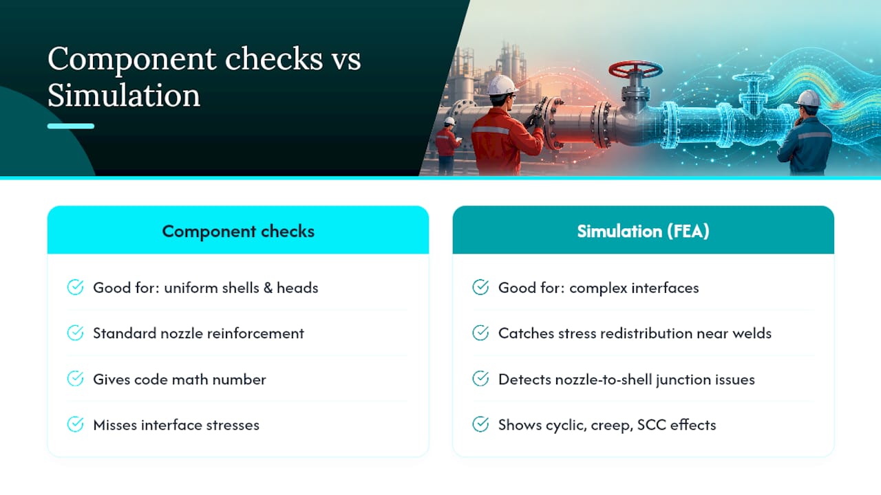
Component-by-component MAWP math handles the straightforward cases well: uniform shells, standard heads, simple nozzle reinforcement. Where it falls short is at interfaces. Thin-to-thick transitions, nozzle-to-shell junctions, and areas with cyclic loading or creep and stress-corrosion-cracking exposure carry stress concentrations that a per-component formula doesn’t capture, and industry commentary consistently flags these as the spots where finite element analysis earns its keep, according to comparative commentary on design pressure and MAWP.
Jewlztech’s complete vessel design guide walks through those interface conditions in more depth, and it’s worth pairing with simulation when a rerating decision is on the table. Simulation catches what a static component check can miss: how hydrostatic effects redistribute stress near a bottom head weld, or whether a rerated vessel still holds up at a nozzle junction under the new operating envelope. Code math tells you the number. Simulation tells you whether that number holds where the geometry gets complicated.
— Joel
Getting MAWP Right Without Redoing the Math by Hand
Hand calculations for component MAWP are manageable for one shell course. They get tedious fast across a full vessel with multiple heads, nozzles, and a liquid fill profile that changes the hydrostatic head at every elevation. Jewlztech’s engineering toolkit is built for exactly that grind: it runs component-level stress checks, applies corrosion allowance and joint efficiency automatically, and lets you test how a rerating scenario shifts the governing component before you commit to a fabrication drawing.

For liquid-service vessels where hydrostatic head is doing real work at the bottom head, the cryogenic pressure vessel and boil-off simulator models fill-level effects directly instead of forcing you to hand-calculate Ph at every elevation. And when the question is whether a stress concentration near a nozzle or thickness transition needs a closer look than a component formula gives you, the thermal analysis toolkit adds coincident temperature effects into the same check. Start with the free toolkit access to see how it handles your current vessel’s numbers, then talk to Jewlztech’s team if you’re working a rerating case that needs a full simulation pass.
FAQ
Is Design Pressure Always Lower Than MAWP?
Not always, but it’s the more common case. Standard plate thickness rounding usually pushes calculated MAWP above the original design pressure, though a vessel can be stamped with MAWP equal to design pressure if no separate calculation was performed.
What Does MAWP Actually Mean on a Nameplate?
It means the maximum gauge pressure the vessel can safely hold at the top, in its installed position, at the coincident temperature listed, based on the weakest calculated component. It is not the same as the pressure the vessel was originally specified to handle unless the two were deliberately set equal.
Do I Need to Calculate MAWP Separately, or Can I Just Use Design Pressure?
ASME Section VIII permits stamping design pressure directly as MAWP, and many simpler vessels do this. Calculating a true component-level MAWP is worth the extra step whenever you expect future rerating, service changes, or need accurate safety relief valve setpoints.
How Does Hydrostatic Head Affect MAWP Calculations?
Static liquid head adds directly to the design pressure at lower components, following P = Pd + Ph, which means bottom heads and lower shell courses in tall liquid-filled vessels often need higher component design pressures than the vessel’s nominal rating suggests.
Can Software Tools Get MAWP Wrong?
Yes, if the inputs for joint efficiency, corrosion allowance, or nozzle reinforcement aren’t modeled correctly, software output can overstate MAWP. Verifying those inputs against the actual fabrication specification before trusting a calculated number is a standard check, and tools like Jewlztech’s simulation toolkit are built to make that verification easier to run.
Recommended
Comments