
Active Cooling Systems: A Technical Guide for Engineers

Updated: 5 days ago

An active cooling system uses external energy, typically electricity, to drive mechanical or electrical components that remove heat from a target surface or environment. Unlike passive approaches that rely on natural convection or radiation, active systems can push temperatures below ambient, which is the defining capability for high-heat flux applications. Core components include fans, pumps, thermoelectric coolers (TECs), and refrigeration cycles. A practical example is the ACS (Active Cooling System) used with uncooled infrared cameras, where a thermoelectric stage keeps the detector array at a controlled temperature to reduce thermal noise and improve image fidelity.
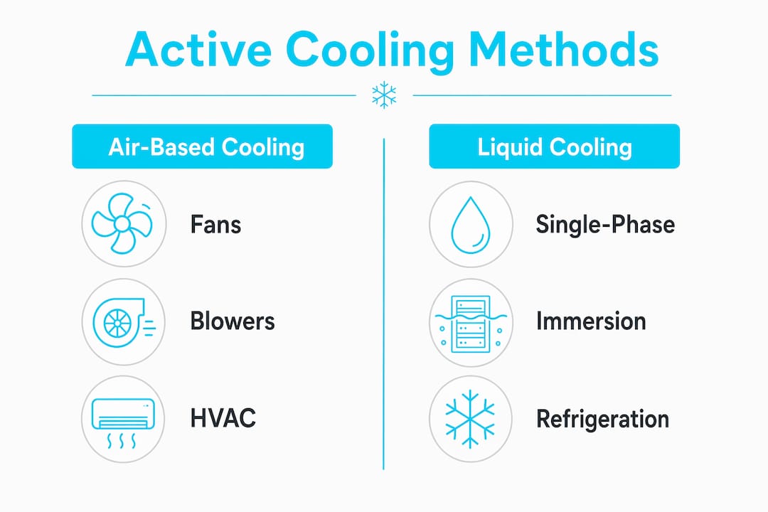
The main categories break down as follows:
Fans and blowers: Force convection overheat sinks; low cost, widely deployed
Liquid cooling loops: Pumps circulate coolant through cold plates or heat exchangers
Thermoelectric coolers: Solid-state Peltier devices that pump heat against a temperature gradient
Refrigeration cycles: Vapor-compression or absorption systems for sub-ambient cooling
Evaporative coolers: Use water evaporation to reduce air temperature, though they consume water in the process
Each type trades energy consumption against cooling capacity differently, and the right choice depends on heat flux density, available space, and acceptable maintenance burden.
Table of Contents
How does an active cooling system compare to passive cooling?
Common types of active cooling systems and where they are used
What recent advances are reshaping active cooling technology?
Engineering insights for designing and implementing active cooling solutions
Design considerations and challenges in active cooling system implementation
Maintenance requirements and operational lifespan of active cooling systems
How does an active cooling system compare to passive cooling?
Passive cooling moves heat through natural convection, conduction to a heat sink, or radiation, with no power input. That simplicity is its main advantage: no moving parts mean near-infinite component lifespan and zero scheduled maintenance. The trade-off is hard thermal limits. Once the heat sink reaches thermal equilibrium with the surrounding air, cooling stops. For low-power electronics or well-ventilated enclosures, that ceiling is acceptable. For a GPU running at 300W in a dense server rack, it is not.
Active cooling breaks through that ceiling by adding mechanical or electrical work to the heat transfer process. Liquid-based cooling is up to 3,000 times more effective than air cooling in certain data center applications, which illustrates just how wide the performance gap can be at high power densities. The cost is energy consumption, mechanical complexity, and periodic maintenance on pumps, fans, and seals.
Dimension | Passive cooling | Active cooling |
Energy consumption | None | Moderate to high |
Cooling capacity | Limited to ambient | Can go sub-ambient |
Application suitability | Low-to-moderate heat flux | High heat flux, dense electronics |
Complexity and maintenance | Minimal; no scheduled service | Mechanical components require inspection and replacement |
Key distinctions worth keeping in mind:
Passive systems suit steady-state, low-power loads where ambient temperatures stay manageable
Active systems are necessary when junction temperatures must stay below a threshold that passive methods cannot reach
Fans have rated MTBF values of 30,000–100,000 hours, but real-world environments with dust, vibration, or elevated temperatures reduce effective lifespan considerably
Noise, vibration, and power draw are active-system penalties that passive designs avoid entirely
For a deeper look at how engineers weigh these trade-offs in practice, the active vs. passive cooling decision guide from Jewlztech covers hybrid approaches and selection criteria in detail.
Common types of active cooling systems and where they are used
Air-based cooling
Fans and blowers are the most common active cooling solution across consumer electronics, industrial controls, and HVAC. A fan forces air across a finned heat sink, increasing the convection coefficient and pulling heat away faster than natural airflow would allow. Blowers, which move air at higher pressure, are preferred in confined enclosures where flow resistance is high. The computer cooling system in a standard desktop tower is a textbook example: a CPU fan, case fans, and a GPU blower all working together to keep junction temperatures within spec.
Liquid cooling technology
Liquid cooling replaces air as the heat transfer medium, exploiting the fact that water has a heat capacity roughly 4,000 times greater than air by volume. A pump circulates coolant through a cold plate mounted directly on the heat source, then through a radiator or heat exchanger where the heat is rejected. Cold plates vary widely in internal geometry, from simple channels to micro-channel arrays that maximize surface area at the chip level. Data centers increasingly use liquid cooling near the heat source because it allows warmer coolant supply temperatures, which improves chiller efficiency and opens the door to free cooling in moderate climates.

Immersion cooling takes this further by submerging electronics in a dielectric fluid. Two-phase immersion systems let the fluid boil on component surfaces, achieving exceptional heat transfer coefficients without a pump moving fluid to a remote heat exchanger.
Thermoelectric coolers
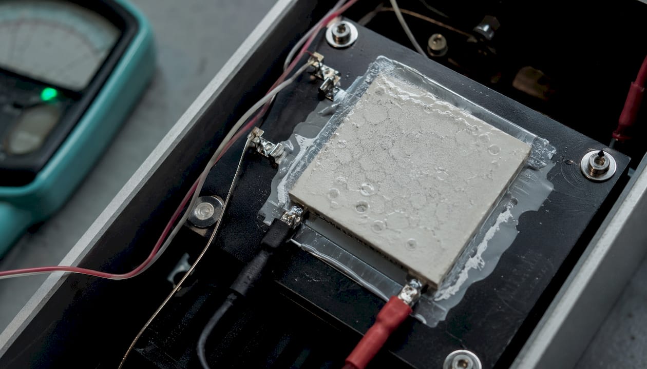
TECs use the Peltier effect: passing a DC current through a junction of two dissimilar semiconductors moves heat from the cold side to the hot side. They have no moving parts, respond quickly to control signals, and can cool below ambient. The ACS for uncooled infrared cameras relies on this principle, holding the detector at a precise temperature regardless of ambient conditions. The penalty is low coefficient of performance (COP); TECs consume considerably more electrical power than they remove as heat, so they are reserved for applications where precision matters more than efficiency.
Refrigeration cycles
Vapor-compression refrigeration drives temperatures well below ambient by cycling a refrigerant through evaporation and condensation stages. Scientific instruments, medical imaging equipment, and some high-performance computing applications use this approach when TECs cannot provide sufficient cooling capacity. Absorption refrigeration substitutes a heat-driven absorber for the compressor, making it viable where waste heat is available but electrical power is limited.
Cooling type | Typical components | Sub-ambient capable | Primary application |
Air (fan/blower) | Fan, heat sink, motor | No | Consumer electronics, HVAC |
Liquid loop | Pump, cold plate, radiator | No (typically) | Servers, EV batteries, industrial |
Thermoelectric (TEC) | Peltier module, heat sink | Yes | Cameras, instruments, small electronics |
Vapor-compression | Compressor, condenser, evaporator | Yes | Scientific equipment, medical devices |
Immersion | Dielectric fluid, heat exchanger | No | High-density data centers |
Pro Tip: When selecting between liquid and air cooling for a computer cooling system, calculate the thermal resistance path from junction to coolant, not just the rated fan airflow. A high-CFM fan paired with a poorly designed heat sink often underperforms a modest pump with a well-matched cold plate.
What recent advances are reshaping active cooling technology?
Hybrid active-passive architectures are the most consequential shift in thermal management right now. Rather than choosing one approach, engineers combine passive heat spreading (vapor chambers, heat pipes) with active heat rejection (fans, liquid loops) to get the reliability of passive components at the chip level and the capacity of active systems at the rack or system level. Google’s Brazos rack-mounted liquid-to-air system is a documented example: it handles heat rejection at the rack without requiring a full facility chilled-water retrofit, which dramatically lowers deployment cost.
Multi-fan active cooling for photovoltaic modules is another area seeing real data. Studies on PV cooling show power generation gains shown to vary widely depending on fan count and conditions when using one to four fans, though the net benefit depends heavily on balancing those gains against the parasitic power the fans consume.
Other developments worth tracking:
Nanofluid coolants: Suspending nanoparticles in base fluids increases thermal conductivity without major changes to pump infrastructure
Modular, retrofit-friendly liquid cooling: Rear-door heat exchangers and in-row cooling units that integrate into existing air-cooled racks without full facility redesign
Near Immersion Active Cooling (NIAC): Originally developed for Wire + Arc Additive Manufacturing (WAAM), NIAC surrounds the work area with a rising coolant level that tracks the deposition process, pulling heat away faster than fixed-level passive liquid cooling
Thermoelectric generators (TEGs): Devices that convert waste heat into electricity via the Seebeck effect, with ongoing research into using that recovered power to partially drive the cooling fan itself
Sustainability is driving much of this. The National Renewable Energy Laboratory’s thermosyphon hybrid system at its High-Performance Computing Data Center saved 4,400 m³ of water in its first year of operation, cutting data center water use by roughly half.
Engineering insights for designing and implementing active cooling solutions
Simulation is the most underused tool in early-stage thermal design. CFD software lets engineers model airflow, conduction paths, and fluid dynamics before cutting a single part, catching problems like recirculation zones or hot spots that would be expensive to fix in hardware. Jewlztech’s Thermalysis Toolkit supports physics-based thermal simulation across conduction, convection, and radiation modes, with a built-in material property database that covers a wide temperature range. Running those simulations at the concept stage, rather than after the enclosure is already designed, is what separates a thermal solution that works from one that requires an expensive redesign.
Pro Tip: Build your thermal budget before you finalize the mechanical envelope. Knowing the maximum allowable junction-to-ambient thermal resistance tells you exactly how much cooling capacity you need, which prevents both over-engineering and under-engineering the system.
Best practices for active cooling design:
Integrate thermal management from the first design review, not as a retrofit
Size the cooling system for worst-case ambient temperature and maximum power dissipation simultaneously
Account for fan or pump degradation over time when setting thermal margins
Plan maintenance access into the enclosure layout; a pump that requires full disassembly to service will not get serviced on schedule
Distinguish between the chip-level cooling loop and the facility-level heat rejection system to optimize each independently
Late-stage cooling integration consistently increases both complexity and cost. Cooling a kilowatt-class component in a constrained form factor after the enclosure is locked is one of the harder problems in electronics packaging, and it is almost always avoidable.
Technical details of active cooling methods
Heat transfer in active systems follows the same governing equations as passive systems, but the boundary conditions change because you control the fluid velocity. Forced convection heat transfer scales with the convection coefficient h, which increases with flow velocity according to the Dittus-Boelter correlation for turbulent internal flow. Higher pump or fan speed raises h, lowers thermal resistance, and reduces component temperature, but at the cost of increased pressure drop and noise.
For liquid loops, the key design parameters are flow rate, coolant inlet temperature, and cold plate thermal resistance. The relationship between this determines the maximum heat load the system can handle at a given junction temperature limit. Micro-channel cold plates reduce thermal resistance by increasing surface area, but they also increase pressure drop, which demands a more powerful pump. That trade-off between thermal performance and hydraulic resistance is central to every liquid cooling design. Engineers working on heat transfer techniques for electronics will recognize this as a classic optimization problem with no single right answer.
Thermoelectric coolers add another layer: COP depends on the temperature differential across the device and the current level, and both interact nonlinearly. Operating a TEC at maximum current does not produce maximum cooling; it produces maximum heat pumping at the cost of high Joule heating that partially offsets the benefit.
Design considerations and challenges in active cooling system implementation
Thermal interface resistance between the heat source and the cooling component is frequently the dominant bottleneck in active cooling designs. A cold plate with excellent internal performance delivers poor results if the thermal interface material (TIM) between it and the chip is applied incorrectly or degrades over time. Thermal paste selection and application directly affects how well heat transfers from the component surface into the cooling loop, even in high-performance systems.
Acoustic noise and vibration are often underweighted in early design. Fans and pumps introduce mechanical vibration that can affect sensitive instruments, fatigue solder joints over time, or simply create unacceptable noise in occupied spaces. Selecting components with low vibration signatures and mounting them on isolation pads addresses most of this, but it requires deliberate planning.
Power budget constraints are another real challenge, particularly in battery-powered or embedded systems. The parasitic power consumed by fans and pumps reduces the net power available for the primary function. For EV battery thermal management, this trade-off is especially sharp: aggressive cooling improves battery longevity but draws from the same energy store that powers the vehicle.
Maintenance requirements and operational lifespan of active cooling systems
Fans rated at 30,000–100,000 hours MTBF sound reliable, but that figure assumes clean air at rated temperature. Dust accumulation on fan blades and heat sink fins reduces airflow and raises thermal resistance, sometimes enough to trigger thermal throttling or shutdown. A quarterly cleaning schedule in dusty industrial environments is not excessive; it is the minimum to maintain rated performance.
Liquid cooling loops require periodic coolant replacement to prevent biological growth, corrosion, and pH drift that degrade tubing and cold plate surfaces. Closed-loop systems with deionized water and corrosion inhibitors typically need a fluid change every two to three years, though this varies with system materials and operating temperature. Pump bearings wear over time and should be treated as a scheduled replacement item rather than a run-to-failure component.
Passive components like heat sinks and vapor chambers have no scheduled maintenance and outlast the systems they cool. That contrast is worth quantifying in any reliability analysis: adding active components to a previously passive design introduces failure modes that did not exist before, and the maintenance plan must account for them from day one.
Case studies: active cooling performance across industries
Data centers: The Lawrence Berkeley National Laboratory’s Chill-Off 2 demonstration compared eleven rack-level liquid cooling devices across multiple chiller plant models. Conduction-based cooling technologies, where thermal blocks conduct heat to a micro-channel top plate, produced the best energy efficiency results, followed by rear-door heat exchangers. The study showed meaningful differences in partial and overall data center efficiency depending on cooling architecture, not just IT equipment power draw.
Photovoltaic systems: Research on multi-fan active cooling for PV modules documented power generation gains of 12.93%–44.34% depending on the number of fans deployed. The critical finding was that net gain depends on the ratio of additional power generated to parasitic fan consumption, which varies with ambient temperature and irradiance conditions.
High-performance computing: NREL’s thermosyphon hybrid cooling system at its HPC data center demonstrated that blending active and passive approaches can cut water consumption by roughly half while maintaining the energy efficiency the facility was already known for.
Additive manufacturing: NIAC cooling for WAAM metal 3D printing showed that active liquid cooling, where coolant level rises dynamically with the deposition process, outperforms both natural air cooling and fixed-level passive liquid cooling in controlling interpass temperatures. Lower interpass temperatures reduce residual stress and improve part quality, making thermal management a direct quality control tool in this application.
Simulate your active cooling design before you build it
Jewlztech’s Thermalysis Toolkit gives engineers a physics-based simulation environment for conduction, convection, and radiation analysis, with variable material properties and a built-in property database. Running your thermal model in the toolkit before committing to hardware lets you validate cooling capacity, identify hot spots, and size components correctly the first time.

Key Takeaways
Active cooling systems outperform passive methods in high-heat flux applications by using external energy to drive forced convection or refrigeration, enabling sub-ambient temperature control that passive designs cannot achieve.
Point | Details |
Sub-ambient capability | TECs and refrigeration cycles drive component temperatures below room ambient, unlike any passive method. |
Liquid vs. air capacity | Liquid-based cooling can be up to 3,000 times more effective than air cooling in data center applications. |
Fan lifespan variability | Fans carry MTBF ratings of 30,000–100,000 hours, but dust and heat reduce real-world lifespan significantly. |
PV cooling gains | Multi-fan active cooling on photovoltaic modules produces power gains of 12.93%–44.34% depending on fan count. |
Early integration saves cost | Integrating thermal management from the first design review prevents expensive retrofits when form factors are already locked. |
Recommended
Comments