
Thermal Shock in Pressure Vessels: NRC Screening Meets Fracture Modeling


BLUF: thermal shock threatens a pressurized vessel when rapid internal cooling hits a wall that is still carrying pressure stress. Check the magnitude and rate of the temperature swing, confirm whether the vessel is pressurized during that swing, compare projected RTPTS or MDMT against screening values, and look for known flaws. When any of those metrics sits close to a limit, escalate to a coupled thermo-hydraulic and fracture-mechanics analysis.
TL;DR:
The NRC technical basis found through wall cracking frequency below 1×10⁻⁸ per reactor year for most operating pressurized water reactors after 40 to 60 years.
Modeled warm prestressing improved apparent resistance to cleavage initiation by 30% to 100%, but that benefit can shrink when ductile tearing controls.
Simplified transient assumptions can understate local risk near nozzles and flanges, where uneven cooling and stress concentrations require geometry specific analysis.
Validate coupled models against documented experiments, because pressure timing changed crack initiation and arrest outcomes in documented thick vessel test series.
Table of Contents
What thermal shock and pressurized thermal shock actually mean
Failure mechanisms and fracture parameters that decide the outcome
Regulatory screening and practitioner thresholds under NRC and ASME
How we approach thermal-shock assessments at Jewlz Technologies
Try a Jewlz Technologies screening before you commit to a full PTS study
What thermal shock and pressurized thermal shock actually mean
Thermal shock is a rapid temperature change at a surface that generates a steep local temperature gradient before the bulk material can respond. In a pressure vessel, this becomes pressurized thermal shock (PTS) when that gradient occurs while the vessel still carries internal pressure, so thermal stress and pressure stress add together at the same location and the same moment.
The physical driver is a mismatch between the cooled (or heated) inner surface and the still-hot bulk wall: the surface wants to contract while the surrounding metal resists, which generates tensile stress right where flaws are most dangerous. Two gradient directions matter:
Radial gradients drive through-wall bending stress, peaking near the inner surface in thick-walled vessels.
Axial gradients appear near nozzles, flanges, and geometric discontinuities, where cold water or gas enters unevenly.
Combined loading happens when pressure-induced hoop stress adds to thermal bending stress at the same depth in the wall, raising the effective stress intensity at a crack tip.
Failure mechanisms and fracture parameters that decide the outcome
Not every thermal transient causes a crack to grow. The outcome depends on whether the controlling fracture mode is brittle cleavage or ductile tearing, and on how close the material’s toughness sits to the applied stress intensity at the transient’s peak.
Cleavage fracture is a low-toughness, often sudden mode that is the primary PTS concern in vessels with irradiation-embrittled or otherwise degraded toughness.
Ductile tearing is a higher-toughness mode that tends to progress more slowly and gives more opportunity for detection or arrest.
Warm prestressing (WPS) describes a loading sequence effect where prior loading at a warmer temperature can inhibit subsequent cleavage initiation during cooling.
Warm prestressing has been quantified in modeled scenarios as providing a 30% to 100% improvement in apparent resistance to cleavage initiation, though that benefit can shrink when ductile tearing becomes the controlling mechanism. This range matters for engineers deciding whether a specific loading history, not just a peak stress value, should factor into an integrity assessment.
A single severe PTS event and cumulative thermal-fatigue damage are distinct risks that call for separate screening. A vessel can pass a single-transient check comfortably yet still accumulate fatigue damage from repeated, smaller thermal cycles over years of start-up and shutdown operation, a point covered in more depth in our guide to thermal-fatigue pitfalls in finite element models.
Regulatory screening and practitioner thresholds under NRC and ASME
For reactor pressure vessels, the U.S. regulatory framework gives engineers a defined screening path rather than leaving PTS risk to judgment alone. The current rule, 10 CFR 50.61, and its risk-informed alternative, 50.61a, both rely on projecting a reference temperature, RTPTS, that accounts for irradiation embrittlement over the vessel’s service life, then comparing it against a defined screening limit.
RTPTS projection combines initial material toughness (RTNDT), neutron fluence, and copper and nickel content to estimate embrittlement at end of license.
Screening thresholds trigger required action when the projected RTPTS approaches or exceeds the regulatory limit, not when it merely rises.
Pressure-Temperature Limits Report (PTLR) updates translate screening results into operational pressure-temperature curves that plant operators must follow.
The NRC’s technical basis for revising PTS screening limits found that, under current operating practices, the through-wall cracking frequency (TWCF) for most operating pressurized water reactors stays below 1×10⁻⁸ per reactor-year even after 40 to 60 years of service, which supported setting RT-based screening limits tied directly to that risk target. A “low” TWCF in this context means the probability of a crack propagating through the full wall thickness during a PTS event is small enough to support continued operation under the existing limits, not that PTS risk disappears.
When a projection approaches the screening value, practical actions include flux-reduction programs to slow further embrittlement, thermal annealing to recover toughness, and plant-specific deterministic or probabilistic fracture-mechanics analyses to justify continued operation with tighter operational limits.
Multi-physics workflows for credible PTS load estimates
Simplified transient assumptions and thin-wall stress formulae tend to underpredict risk near nozzles, flanges, and other geometric discontinuities, where local cooling rates and stress concentrations diverge sharply from the bulk vessel behavior. Coupled multi-physics simulation, combining thermo-hydraulic, thermo-mechanical, and fracture-mechanics models, gives a more realistic picture of how a transient actually loads a flaw.
A credible PTS assessment generally follows this sequence:
Transient thermo-hydraulic analysis establishes local wall cooling rates under the actual injection or upset scenario, not a bounding average.
Inverse heat conduction or transient FEA reconstructs the inner-surface temperature history from fluid-side boundary conditions, a method detailed in our practical FE workflow for pressure vessel thermal analysis.
Elastoplastic stress analysis converts that temperature history into through-wall stress, accounting for temperature-dependent yield and modulus.
Fracture-mechanics assessment, deterministic or probabilistic, compares applied stress intensity against material toughness at the flaw tip.
Key inputs include the emergency core cooling (ECC) injection scenario, temperature-dependent material properties, a flaw size and location database, and a mesh fine enough to resolve stress gradients near nozzles. Probabilistic fracture mechanics (PFM) suits cases where flaw distributions are uncertain and a risk metric like TWCF is the target output; deterministic FEM crack assessment suits a specific, postulated flaw and a pass/fail margin check.
Pro Tip: Validate any coupled thermal-structural model against a documented experimental case before trusting its output near a screening threshold.
Experimental evidence and representative case studies
Physical testing remains the anchor for validating PTS models, because coupled simulations can diverge from reality near complex geometry if boundary conditions are mis-specified.
Thick-vessel PTS experiments have produced both crack initiation and crack arrest episodes within the same test series, including one documented arrest at roughly 88 K above RTNDT with a stress intensity near 299 MPa·√m.
Changing the loading sequence, for instance applying pressure before or after the thermal transient, shifted outcomes between initiation and arrest in these tests, confirming that warm prestressing effects are sequence-dependent rather than fixed.
These experimental boundary cases are what modelers use to check that a computational model neither overstates nor understates crack growth potential, rather than trusting the model in isolation.
Practical mitigation, monitoring, and operational controls
Reducing PTS risk starts at the design stage and continues through daily operation.
Design controls: minimize stress concentrators near nozzles and flanges, select materials with favorable toughness transition behavior, and route cold-fluid inlets away from geometry that traps cold spots.
Operational controls: limit the rate of temperature change (ΔT/Δt) during start-up and shutdown, manage burner or injection cycling, and follow monitored heating and cooling curves rather than ad hoc operation.
Remedial options: warm prestressing exploits favorable loading sequences where operationally possible, thermal annealing restores toughness in embrittled material, and flux-reduction programs slow further degradation in reactor applications specifically.
Monitoring: inverse heat-conduction techniques reconstruct inner-surface temperature from external measurements, and online thermal-stress monitoring in boiler and thick-walled cylinder applications flags excursions beyond allowable heating or cooling rates before they become damaging.
Pro Tip: A documented allowable heating and cooling rate curve, posted at the control panel, prevents more PTS exposure than any single analysis report.
Insulation choices and corrosion-under-insulation conditions also affect how a vessel wall responds thermally, a factor worth reviewing alongside insulation and CUI considerations during design review.

How we approach thermal-shock assessments at Jewlz Technologies
Our Jewlz Engineering Toolkit combines conduction, convection, and radiation modeling with a built-in material property database, so a screening-level thermal check does not require a separate paid license for each physics domain.
We support screening-level checks first: temperature gradient, approximate thermal stress, and a quick comparison against known material limits.
For deeper work, our pressure vessel simulation tools and finite difference heat solver walkthrough extend that screening into a full transient conduction and stress workflow.
We recommend starting with the free screening tools, then moving to detailed coupled simulation once any metric sits close to a screening threshold.
Balancing modern modeling against regulatory conservatism
Multi-physics evidence can justify relaxing a conservative assumption only when the underlying model has been validated against a documented experiment and the assumptions are written down for review. Where validation is thin or a flaw’s history is uncertain, regulatory conservatism should prevail over a more optimistic simulation result. A second engineer reviewing the assumptions catches more errors than a sharper model ever will.
— Joel
Try a Jewlz Technologies screening before you commit to a full PTS study
A full coupled PTS analysis takes real engineering hours, so running a fast screening first saves effort on vessels that clearly sit far from any threshold. Our Jewlz Engineering Toolkit lets you check conduction, convection, and radiation effects together with a built-in property database, so you are not assembling separate spreadsheets for each heat-transfer mode.
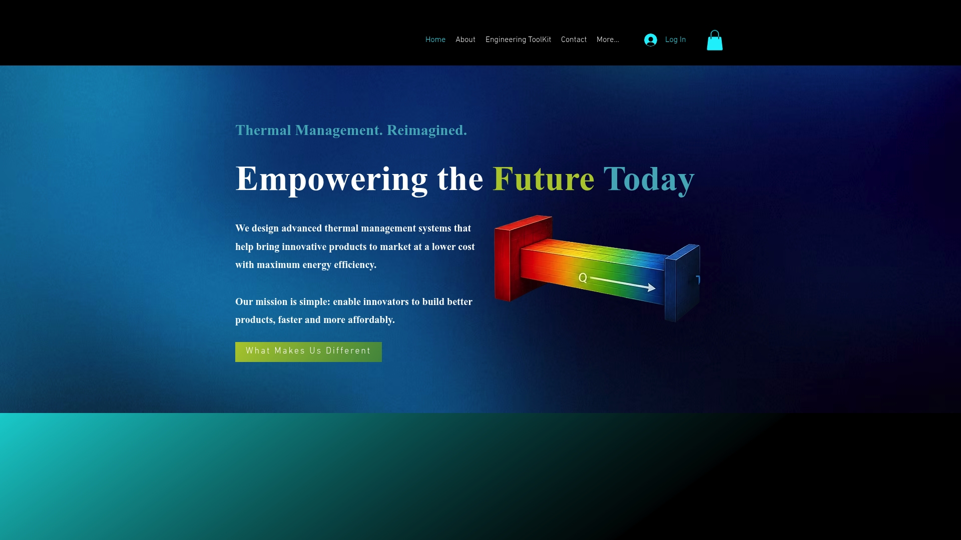
Start with a thermal analysis screening to size your temperature gradient and approximate thermal stress.
Move to our cryogenic pressure vessel and boil-off simulator when your scenario involves rapid cooling or cryogenic fill operations.
Visit the engineering toolkit to see current subscription options for the full coupled workflow.
FAQ
What causes thermal shock in a pressure vessel?
Thermal shock happens when a surface heats or cools faster than the surrounding material can follow, creating a steep local temperature gradient. In a pressurized vessel, this gradient generates thermal stress that adds to existing pressure stress, which is why rapid cooling during an upset condition is the typical trigger.
What is the difference between a boiler and a pressure vessel?
A boiler is a specific type of pressure vessel designed to generate steam or hot water by applying heat to a contained fluid. A pressure vessel is the broader category, covering any sealed container designed to hold a fluid at a pressure different from ambient, whether or not heat generation is involved.
How do you calculate MDMT for a pressure vessel?
Minimum design metal temperature (MDMT) is determined from the vessel’s material toughness, wall thickness, and applicable ASME code exemption curves, which set the lowest temperature at which the material maintains adequate fracture resistance under design loads. Our FE workflow for pressure vessel thermal analysis walks through how transient temperature data feeds into this kind of toughness-based check.
What is the main purpose of a thermal shock chamber?
A thermal shock chamber subjects a test specimen or component to rapid, controlled temperature swings to evaluate how it responds to thermal cycling stress before it goes into service. For pressure vessel materials, this kind of controlled testing helps validate toughness and fatigue behavior against the same mechanisms that drive real-world thermal shock.
When should an engineer escalate to coupled multi-physics simulation?
Escalate when a projected RTPTS, MDMT comparison, or known flaw sits close to a regulatory or material screening limit rather than comfortably below it. At that point, a coupled thermo-hydraulic and fracture-mechanics simulation gives a more realistic risk picture than a simplified bounding calculation.
Sources
Recommended
Comments