
Engineers: Pressure Vessel Insulation to Prevent CUI, ASME, API, CFD

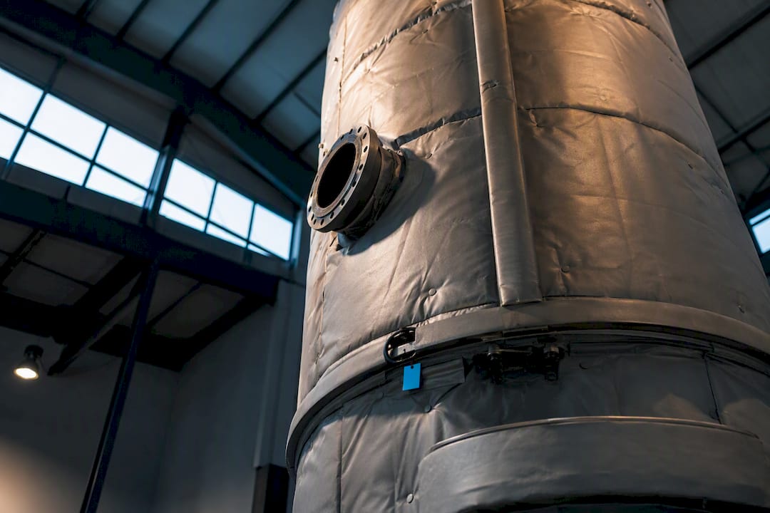
Match insulation material to service temperature and moisture exposure, then build a weather/vapor barrier that keeps water out of the system entirely. That combination, not the insulation material alone, is what stops corrosion under insulation (CUI) before it starts. ASME BPVC governs the vessel design side, API 510 governs inspection, and ASTM E398 sets the permeance benchmark for the barrier. For wet or corrosive service, cellular glass is the standard choice because it will not absorb water; for dry, stable environments, a permeable jacket over mineral wool or calcium silicate often performs just as well at lower cost.
TL;DR:
Cellular glass is ideal for wet or corrosive environments because it resists water absorption and prevents capillary-driven corrosion under insulation.
Proper insulation system design must include weather barriers, drainage, and support rings spaced effectively to prevent sagging and water pooling.
Specifying a vapor permeance below 2 perms in the weather barrier significantly reduces moisture ingress and delays corrosion by limiting water migration.
Field installation practices like prefabricating panels and staggering joints greatly improve long-term insulation integrity and CUI prevention.
Transient finite element analysis and CFD simulations are essential for accurately predicting heat loss, thermal stresses, and cyclic fatigue in vessels subjected to temperature fluctuations.
Table of Contents
Pressure Vessel Insulation Materials by Temperature and Moisture Risk
Six materials cover almost every industrial pressure vessel application, and each one earns its place through a different combination of temperature range, density, and how it behaves when water gets in.
Mineral wool handles roughly 1,200°F to 1,800°F depending on formulation, runs a thermal conductivity around 0.023 to 0.035 W/m·K at mid-range temperatures, and comes in blanket or board form. It absorbs moisture readily and loses R-value once wet, so it belongs in dry, well-jacketed applications rather than buried or frequently wetted locations.
Calcium silicate covers roughly 200°F to 1,200°F, offers strong compressive strength in board form, and tolerates some moisture better than mineral wool, though it still wicks water through capillary action. It is a common choice for walkable vessel tops because it resists crushing under foot traffic and light equipment.
Cellular glass spans cryogenic temperatures up to around 900°F and is the only fully nonabsorbent insulation commonly specified, which is why it dominates corrosive, wet, and below-ambient service. It costs more than fibrous alternatives, but that price buys immunity to the capillary wicking that drives most CUI failures.
Aerogel blankets deliver the lowest thermal conductivity of the group, often near 0.014 W/m·K, and fit tight annular spaces where clearance is limited. They cost significantly more per unit volume, so they show up mainly on high-value, space-constrained systems rather than large storage vessels.
Polyurethane and closed-cell foams work well from cryogenic temperatures up to around 250°F and are common on chilled and refrigerated vessels, but they degrade above that range and are unsuitable near chloride-sensitive stainless steel because of additive leaching.
Ceramic fiber handles the highest end of the range, often exceeding 2,000°F, and comes as blanket, board, or vacuum-formed shapes for furnace and high-temperature reactor applications where mineral wool would break down.
Multilayer insulation (MLI) sits outside this list because it solves a different problem: radiative heat transfer in vacuum-jacketed cryogenic vessels, not conductive loss in atmospheric equipment. For anything touching liquefied gas storage, MLI performance data belongs alongside a proper cryogenic simulation rather than a generic conductivity table.
Designing Insulation Systems for Large and Vertical Vessels
Vessel geometry drives more insulation decisions than most specifications acknowledge. A 40-foot vertical column with a dozen nozzles behaves nothing like a small horizontal tank, and the insulation system has to account for that from the drawing stage.
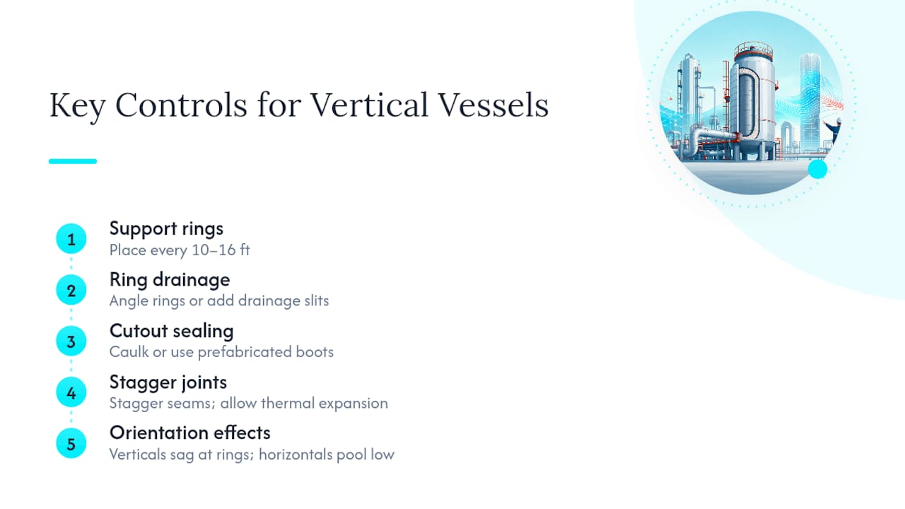
1. Space support rings correctly. Welded support rings typically go in every 10 to 16 feet on vertical runs to carry the insulation’s own weight and keep it from settling and cracking the jacket below. Space them too far apart and the insulation column sags; too close and you multiply the number of penetration points where the weather barrier can fail.
2. Build drainage into every ring. A flat support ring is a shelf that collects condensation. Angle the ring or cut drainage slits into it so water sheds outward instead of pooling against the vessel wall, where it will sit undetected for years.
3. Treat cutouts as their own design problem. Manways, nozzles, and instrument penetrations each need caulking, flashing, or a prefabricated boot rather than field-improvised wrapping. Every cutout is a potential leak path, and the more of them a vessel has, the more that favors prefabricated insulation panels over field-cut blanket.
4. Stagger joints and allow for expansion. Butt every seam in a single plane and you create a straight thermal short and a crack line once the jacket expands and contracts. Staggering layers, the way brick courses overlap, forces any moisture path to travel sideways before it reaches metal.
5. Account for orientation. Vertical vessels concentrate load on support rings and are more prone to sagging over time; horizontal vessels distribute weight along saddle supports but create low points at the bottom quarter where water collects first.
Pro Tip: Where scaffolding access is limited or expensive, specify prefabricated insulation panels before the job starts rather than mid-project. Field fabrication under scaffold constraints is where most sealing defects originate.
Corrosion Under Insulation: Causes and the Five-Factor Prevention Strategy
CUI starts the moment water gets past the weather barrier and finds a path to bare metal, usually through a cracked jacket seam, a failed caulk joint, or a support ring with no drainage. Once inside, water moves through the insulation by capillary action, and depending on the chemistry involved, it drives chloride-induced pitting on stainless steel or general acidic or alkaline attack on carbon steel. Nonbreathing metal jackets make this worse, not better, because they trap moisture against the vessel wall instead of letting it evaporate outward.
The permeance number that matters: ASTM E398 sets an acceptable water vapor permeance for weather and vapor barriers at roughly 2 perms. Specify a barrier below that threshold and you materially cut the moisture volume that can migrate into the insulation system over time.
The National Board’s guidance on CUI prevention breaks the problem into five factors, and skipping any one of them tends to undercut the other four:
Insulation selection — choose a material with low moisture retention for wet-prone zones; cellular glass for corrosive or flammable liquid service, calcium silicate or mineral wool where conditions stay dry.
Equipment design — simplify the vessel surface. Fewer protrusions and simpler support details mean fewer places for water to find a way in.
Protective coatings — a highly permeable coating can let corrosion start behind an intact-looking surface, so match coating chemistry to temperature, abrasion exposure, and immersion risk rather than defaulting to a generic primer.
Weather/vapor barrier design — this is the layer you can actually inspect and repair economically over the vessel’s life, which is exactly why it deserves the most design attention up front.
Maintenance and inspection — the National Board recommends planning weather jacket maintenance on a 2 to 5 year cycle and full recoating on a 10 to 15 year cycle, tied into a broader inspection program under API 510.
Stainless steel needs an extra qualifier here: insulation used against austenitic stainless should meet MIL-I-24244 or ASTM C-795 chloride limits, since even trace chloride leaching from an ordinary fibrous insulation can trigger stress corrosion cracking under the jacket. Where steam tracing runs inside the insulation cavity on stainless vessels, that risk compounds further, and foil separators or chloride-free formulations become worth the added cost.
Sizing Insulation Thickness for Heat Loss and Fatigue Life
Thickness selection starts with five inputs: operating temperature, ambient temperature, the insulation’s thermal conductivity at mean temperature, target surface temperature (often 140°F for personnel protection), and an acceptable heat-loss rate per unit area. For straightforward atmospheric vessels running at steady state, tabulated thickness charts from major insulation manufacturers get you close enough for a first pass.
That approach breaks down fast once the vessel sees thermal cycling, jacketed heating, or transient startup and shutdown. In those cases, hand calculations understate what actually happens at the metal surface, and the gap matters more than engineers often expect.
Thinner or poorly matched insulation lets the vessel wall track ambient swings more closely, widening the thermal gradient across the shell on every cycle.
Wider gradients translate directly into higher cyclic thermal stress, and insulation choices measurably affect fatigue life by either damping or amplifying that stress range.
Vessels with frequent startup/shutdown cycles, jacketed heating loops, or cryogenic boil-off dynamics need transient FEA, not steady-state hand math, to catch stress concentrations at nozzles and support attachments.
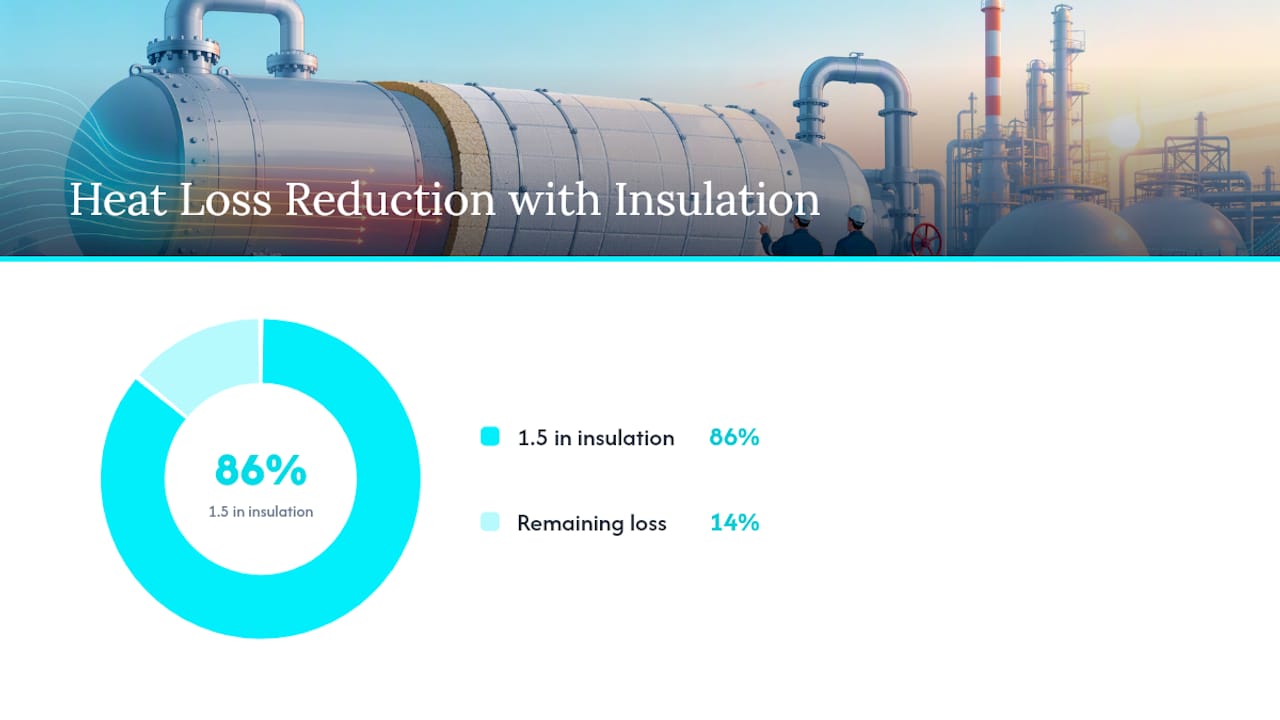
For jacketed heating systems specifically, a CFD run before finalizing insulation specs catches convective loss patterns that a simple conductivity calculation misses entirely. And for a concrete sense of what insulation thickness actually buys you, one case study on a straight run of process piping found that 1.5 inches of fiberglass cut heat loss by 86 percent compared to bare pipe. Vessel geometry differs from piping, but the order of magnitude is a useful sanity check against tabulated numbers.
Field Installation and Maintenance Practices That Actually Hold Up
Good specifications fail in the field when installation crews improvise around access constraints. Building the sequence into the spec up front avoids most of that.
1. Prefabricate wherever scaffolding is tight. Panels cut and fitted in a shop seal better than blanket insulation hand-wrapped forty feet up on a swing stage.
2. Stagger every layer and joint. No two seams should line up radially or longitudinally across adjacent layers.
3. Choose fasteners deliberately. Weld pins hold insulation tight against vibration-prone vessels; stainless bands under tension work better on smooth cylindrical sections where welding isn’t practical or is restricted by the base metal.
4. Pick jacketing material based on inspection needs, not just cost. Metal jacketing (aluminum or stainless) resists mechanical damage well but can hide a slow leak behind a seam for years. Plastic or synthetic jackets show water staining and damage more visibly, trading some durability for earlier leak detection.
5. Focus inspections on the failure-prone spots first. Low points on horizontal runs, every support ring, and every cutout around a nozzle or manway account for the overwhelming majority of CUI findings during turnaround inspections.
Pro Tip: Photograph and log every support ring and cutout location at initial installation. When API 510 inspection intervals come around, that baseline record cuts inspection time dramatically because crews know exactly where to look first.
Standards and Codes That Govern Pressure Vessel Insulation
A handful of standards define nearly every specification decision covered above:
ASME BPVC sets the design rules for the vessel itself and defines where insulation supports and penetrations can attach without violating pressure boundary integrity.
API 510 governs in-service inspection intervals and scope for pressure vessels, including how CUI-prone insulated sections get examined during turnarounds.
National Board guidance provides the practical CUI prevention framework referenced throughout this piece, including maintenance cadence recommendations.
ASTM E398 defines the water vapor permeance test method behind the 2-perm weather barrier benchmark.
MIL-I-24244 and ASTM C-795 set chloride limits for insulation used against austenitic stainless steel, directly shaping which materials are acceptable near stress-corrosion-sensitive equipment.
Specification language should cite these directly rather than paraphrasing them, since inspectors and third-party auditors check compliance against the exact standard text.
When to Escalate From Hand Calculations to Simulation
Hand calculations and tabulated charts are fine for steady-state, low-consequence vessels. The moment cyclic loading, jacketed heating, or cryogenic boil-off enters the picture, a static calculation stops telling you what you need to know.
Use steady-state heat-loss equations to set an initial thickness estimate and confirm it against manufacturer tables.
Escalate to transient FEA when the vessel cycles frequently, since thermal gradients drive fatigue accumulation in ways steady-state math cannot capture.
Run CFD on jacketed vessels where convective currents inside the jacket annulus affect the outer wall temperature profile.
Model cryogenic vessels for boil-off rate directly, since insulation performance there ties straight to product loss economics, not just surface temperature comfort.
A practical workflow: define boundary conditions, run a steady-state estimate, confirm with transient modeling for any cyclic service, then iterate thickness and jacketing detail until the model and the specification agree.
Why Design-Time Coordination Beats Field Fixes
The costliest insulation mistakes I’ve seen described in industry case studies never trace back to bad material choice. They trace back to process, mechanical, and insulation disciplines working from separate drawings that never got reconciled before fabrication.
A support ring with a drainage slit costs almost nothing to specify at the drawing stage. Retrofitting drainage into a ring that’s already welded, jacketed, and buried under ten years of coating means stripping insulation off a live vessel. Get the weather jacket detail and the support ring drainage right before steel gets cut, and CUI risk drops more than any material upgrade downstream ever will.
— Joel
Model Your Insulation Choices Before You Specify Them
Picking a material off a chart tells you the theory. Running the actual heat-loss and thermal-stress numbers for your specific vessel geometry tells you whether that choice holds up under real operating cycles. Jewlztech’s CFD simulation software models convective losses and transient behavior in jacketed and insulated systems, while the cryogenic pressure vessel simulator quantifies boil-off directly for cryogenic storage. If your project involves heat exchanger surfaces alongside vessel insulation, the heat exchanger optimization tool covers that side of the thermal system too. Free demos are available for engineers who want to test a specific geometry before committing to a spec, and the sales team takes on project-specific modeling work for teams that need a faster answer than a full in-house simulation build. Start with a quick model of your vessel’s heat-loss profile before finalizing thickness and jacketing decisions.
Sources
FAQ
What is the best material for insulating pressure vessels?
There is no single best material; cellular glass is the standard choice for wet or corrosive service because it is fully nonabsorbent, while mineral wool or calcium silicate work well in dry, stable environments at a lower cost.
How can I insulate a well pressure tank?
Residential pressure tanks typically use a fitted foam or fiberglass insulation blanket sized to the tank’s dimensions, mainly to prevent freezing and condensation rather than to meet an industrial heat-loss target.
What type of insulation is used for boilers?
Boilers commonly use calcium silicate or mineral wool for the main shell insulation, with ceramic fiber reserved for refractory-adjacent areas and firebox linings where temperatures exceed what fibrous mineral insulation can handle.
What is the best insulation blanket for a pressure tank?
For small residential or commercial tanks, a closed-cell foam or fiberglass blanket rated for the tank’s operating temperature offers the best balance of moisture resistance and ease of installation; for industrial vessels, a cellular glass or mineral wool blanket sized against the 2-perm barrier standard performs better long term.
Recommended
Comments