
Thermal Runaway Prevention: An Engineer's Complete Guide

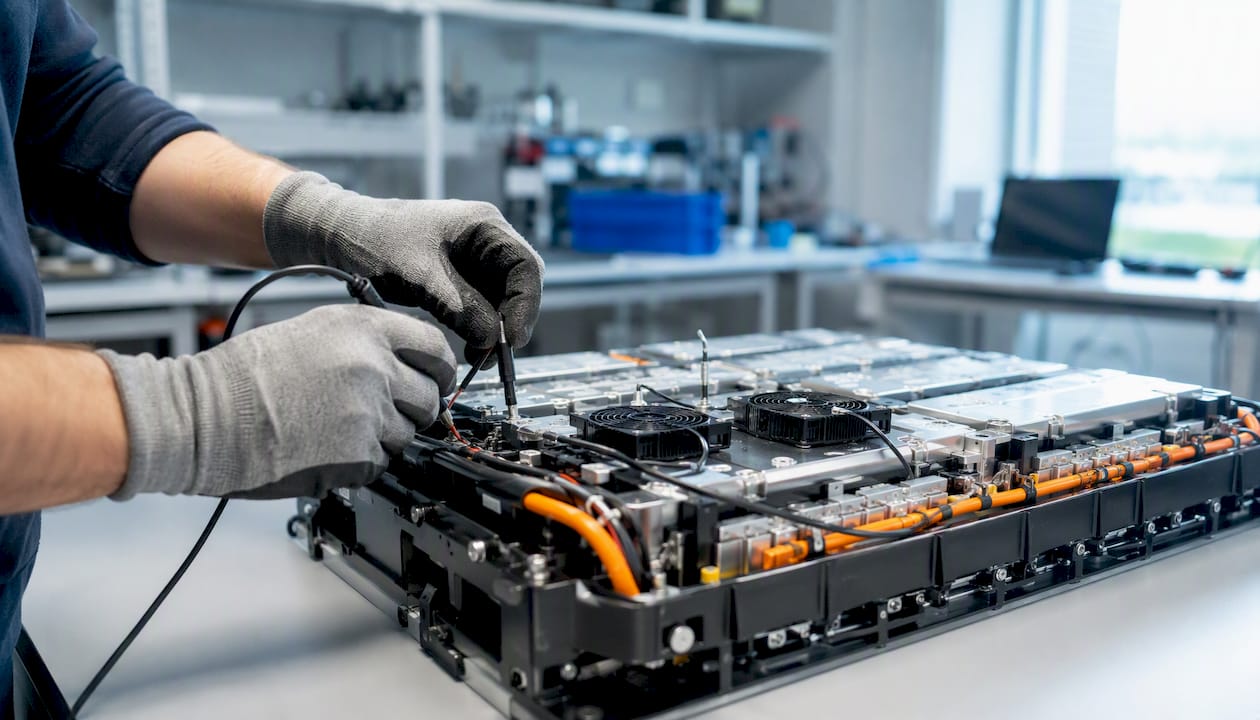
Thermal runaway in lithium-ion systems is best stopped with a layered defense: intrinsic cell safeguards, simulation-validated pack thermal management, and a multi-signal BMS that isolates faults before reactions become irreversible. No single mechanism is sufficient on its own. The engineering record is clear on this.
Three immediate actions follow from that claim. First, specify PTC thermistors, current interrupt devices (CIDs), and shutdown separators at the cell level as baseline requirements, not optional features. Second, validate your cooling architecture through physics-based simulation so heat removal capacity exceeds worst-case heat generation under abuse conditions. Third, build your BMS to fuse temperature, pressure, voltage, and gas signals together, then automate isolation and shutdown responses with latency low enough to act before the exothermic cascade locks in.
The relevant U.S. standards to anchor your design reviews are UL 9540A for abuse and propagation testing, NFPA guidance on safe charging and storage, and OSHA’s Hierarchy of Controls framework for workplace battery hazards. Those three documents, taken together, define the minimum credible safety program for any team working on lithium-ion packs in the United States.
Require PTC/CID/shutdown separators at the cell level
Validate cooling capacity via simulation before hardware prototyping
Implement multi-signal BMS detection with automated isolation
Reference UL 9540A, NFPA, and OSHA controls in design documentation
Plan for propagation, not just single-cell failure
Key Takeaways
Thermal runaway prevention requires a layered defense combining cell-level safeguards, simulation-validated pack thermal management, multi-signal BMS detection, and documented operational controls referenced to U.S. standards.
Point | Details |
Cell-level safeguards are necessary but not sufficient | PTC thermistors, CIDs, and shutdown separators protect single cells but cannot stop propagation in large multi-cell packs without pack-level barriers. |
Simulation must validate heat removal capacity | Physics-based CFD and multi-physics models must confirm heat removal exceeds worst-case heat generation before hardware prototyping begins. |
Multi-signal BMS outperforms temperature-only monitoring | Fusing pressure, gas, voltage, and temperature signals provides earlier warning and more reliable detection than any single-sensor approach. |
U.S. standards define the certification roadmap | UL 9540A, NFPA 855, IEC 62133, and OSHA guidance each address a distinct phase of the design and operations program; all are required. |
Thermalysis Toolkit supports validation workflows | Jewlztech’s Thermalysis Toolkit provides the PCM, conjugate heat transfer, and CFD simulation tools needed to generate design-review-ready validation metrics. |
Table of Contents
Why thermal runaway is dangerous and what early indicators to watch
A prevention framework: applying the Hierarchy of Controls to battery systems
What cell-level safety features actually do and where they fall short
Battery management systems: detection, state estimation, and mitigation
U.S. standards and certification pathways you need to reference
Operational best practices: storage, charging, and maintenance
Simulation-led validation: CFD, multi-physics modeling, and verification steps
Where design teams typically get thermal runaway prevention wrong
The Thermalysis Toolkit gives your team a simulation edge on thermal safety
How thermal runaway starts: mechanisms and common triggers
Thermal runaway is not a single event. It is a self-reinforcing sequence that begins well before a cell vents or catches fire.
The initiating stage is solid electrolyte interphase (SEI) decomposition. Above roughly 80–120°C, the SEI layer on the anode surface breaks down exothermically, releasing heat that accelerates further decomposition. That heat drives the next stage: reaction between the intercalated lithium in the anode and the electrolyte solvent, generating more heat and flammable gases. At higher temperatures, cathode decomposition releases oxygen, which feeds electrolyte combustion directly inside the cell. Pressure builds from gas evolution, and if the cell vent does not activate in time, or if the vent capacity is undersized, mechanical rupture follows.
The mechanisms and prediction approaches reviewed in the literature confirm that this cascade is strongly nonlinear: the rate of heat generation increases faster than the rate of heat dissipation once the process passes a threshold temperature, which is why early detection matters far more than late-stage suppression.
Common initiating triggers fall into four categories:
Mechanical abuse: crush, penetration, or deformation that causes an internal short circuit between anode and cathode
Electrical abuse: overcharge (driving lithium plating and dendrite growth), over-discharge, or external short circuit
Thermal abuse: sustained elevated ambient temperature, localized hot spots from poor thermal design, or heat propagation from an adjacent cell already in runaway
Manufacturing defects: metallic particle contamination, tab weld failures, separator pinholes, or electrolyte fill inconsistencies that create latent internal short paths
Failure modes engineers should model explicitly include tab weld fracture under vibration, separator puncture from dendrite growth during repeated overcharge cycles, and cell-to-cell imbalance in large series strings that drives individual cells into overcharge while the pack voltage appears nominal.
Why thermal runaway is dangerous and what early indicators to watch
The hazard profile goes beyond fire. A cell in runaway generates temperatures that can exceed 700°C locally, produces toxic decomposition gases including hydrogen fluoride (HF) and phosphoryl fluoride (POF₃), and builds internal pressure that can rupture the casing and eject hot fragments. In a multi-cell pack, the heat from one cell can propagate to neighbors, triggering a cascade that overwhelms any single suppression measure.
UL’s guidance on thermal runaway causes identifies the toxic gas hazard as a primary concern for first responders and facility personnel, not just the fire itself. HF in particular is acutely toxic at low concentrations and is generated during electrolyte decomposition even when visible flames are absent.
Early indicators engineers should build into monitoring and test plans:
Abnormal temperature gradients across the pack, particularly a single cell or module running 5–10°C above neighbors under identical load
Unexpected pressure rise inside a sealed enclosure or individual cell housing before any thermal event is visible
Rapid voltage deviation on a single cell: a sudden drop under load or an anomalous open-circuit voltage suggests internal short or electrolyte degradation
Gas venting or odor: electrolyte vapor and decomposition gases are detectable before thermal escalation becomes visible
Acoustic signatures: popping or hissing from a cell under normal operating conditions indicates internal gas evolution
Statistic callout: Multi-physics signal fusion research shows that combining pressure, gas composition, voltage variance, and temperature signals yields earlier warning and higher detection reliability than temperature monitoring alone, giving the BMS more lead time to act before irreversible reactions begin.
Each indicator maps to a BMS action. A temperature gradient anomaly triggers increased sampling rate and coolant flow. A pressure spike triggers cell isolation. A voltage deviation triggers segment shutdown and logging for post-event analysis. Designing those mappings explicitly, before the system ships, is what separates a reactive safety system from a predictive one.
A prevention framework: applying the Hierarchy of Controls to battery systems
OSHA’s Hierarchy of Controls provides the right prioritization logic for battery safety programs. Applied to lithium-ion systems, the hierarchy runs from most to least effective: elimination and substitution at the top, then engineering controls, then administrative controls, with PPE at the bottom.
Elimination means removing the hazard entirely. For battery systems, that translates to chemistry selection: solid-state electrolytes and lithium iron phosphate (LFP) cathodes carry substantially lower thermal runaway risk than NMC or NCA chemistries at equivalent energy density. When the application allows it, choosing a more thermally stable chemistry is the single highest-leverage decision in the entire safety program.
Engineering controls cover the bulk of the work: cell-level safeguards (PTC, CID, shutdown separators), validated pack thermal management, BMS architecture, containment structures, and pressure relief paths. These controls are effective because they operate automatically, without depending on human behavior.
Administrative controls, including charging SOPs, storage quantity limits, inspection schedules, and emergency response training, are necessary but insufficient on their own. A facility that relies primarily on procedures rather than engineered safeguards is one human error away from a serious incident.
Pro Tip: During concept design, run a Failure Mode and Effects Analysis (FMEA) that maps each initiating trigger (mechanical, electrical, thermal, manufacturing) to the specific engineering control that addresses it. Any trigger without a corresponding engineering control should be escalated before the design review closes, not resolved with a procedure.
A practical prioritization checklist for concept and detailed design phases:
Chemistry and cell format selection (LFP vs. NMC vs. NCA; cylindrical vs. prismatic vs. pouch)
Cell-level safeguards specified and verified in cell datasheet
Cooling architecture sized by simulation against worst-case heat generation
BMS signal architecture defined (sensors, fusion logic, response actions)
Propagation barriers and containment structures designed and tested
Administrative controls and emergency response plan documented
What cell-level safety features actually do and where they fall short
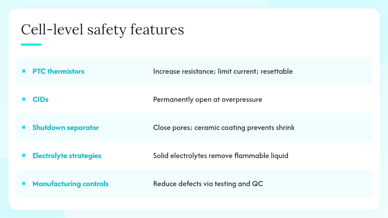
Cell-level safeguards are the first line of defense, and the published review of safety methods describes their mechanisms and limits in detail.
PTC thermistors are positive temperature coefficient resistive elements placed in series with the cell circuit. As temperature rises, resistance increases sharply, limiting current and reducing heat generation. PTC electrodes embedded directly in the electrode stack offer faster response than external PTC devices because they sense temperature at the reaction site rather than at the cell surface. The limitation: PTC devices are designed for single-cell protection and can reset after cooling, which means they do not permanently isolate a degraded cell.
Current interrupt devices (CIDs) are mechanical switches that open permanently when internal pressure exceeds a set threshold, typically from gas evolution during overcharge or thermal abuse. Once triggered, the cell is electrically isolated. The design challenge in multi-cell arrays is that a CID activation in one cell can create a voltage imbalance that drives adjacent cells into overcharge if the BMS does not respond quickly.
Shutdown separators are engineered to melt or close their pores at elevated temperature, blocking ion transport and halting electrochemical reactions. Ceramic-coated separators add mechanical stability so the separator does not shrink and create a short circuit at the same temperature that closes its pores. This is a meaningful distinction: a separator that shuts down ion flow but then contracts and shorts the cell has not solved the problem.
Electrolyte strategies include flame-retardant additives (phosphazene compounds, for example), alternative lithium salts with higher thermal stability, and gel or solid electrolytes. Solid electrolytes eliminate the flammable liquid entirely, which is the most effective electrolyte-level intervention, but current solid-state cells trade off ionic conductivity and manufacturing scalability.
Manufacturing controls matter as much as any device. Clean-room assembly, in-line particle detection, tab weld quality inspection, and end-of-line (EOL) electrical testing to catch latent internal shorts before cells leave the factory reduce the baseline defect rate that drives field failures.
The critical caveat, confirmed by lab programs including NASA testing: PTC and CID protections that work reliably on single cells can fail to stop propagation in large multi-cell packs. The thermal and electrical coupling between cells in a high-energy pack overwhelms single-cell isolation mechanisms. Pack-level barriers and propagation testing are not optional supplements to cell-level safeguards. They are required.
Advances in prevention research confirm that combining PTC thermistors, CIDs, shutdown separators, electrolyte innovations, and BMS interventions as complementary layers is the standard approach for pack safety, not a belt-and-suspenders excess.
How pack and system design stops heat from spreading
Pack-level thermal management is where the largest engineering decisions get made, and where simulation validation is non-negotiable. The core requirement, supported by thermal management process research, is that heat removal capacity must exceed peak heat generation under worst-case duty cycles, not just nominal operation.
Active vs. passive cooling: where each wins
Active cooling uses forced liquid (typically water-glycol or dielectric fluid) or forced air circulated through channels adjacent to cells or modules. Liquid cooling delivers higher heat transfer coefficients and handles high-power applications well, but adds plumbing complexity, pump failure modes, and leak risk. Forced air is simpler and lighter but struggles with high cell-to-cell uniformity requirements in dense packs.
Passive cooling uses phase change materials (PCMs), heat pipes, or thermal fins. PCMs absorb transient heat spikes through latent heat of fusion, which is particularly useful for pulsed-load applications where peak heat generation is brief. The design trap with PCMs is that they work only until their latent capacity is exhausted. If the subsequent steady-state heat dissipation path is not sized correctly, the PCM saturates and the pack temperature climbs anyway. Simulate the phase-change transient and the post-saturation steady state, not just the absorption phase.
Hybrid systems (liquid cooling combined with PCM buffering, or heat pipes feeding a liquid cold plate) deliver the best of both: the PCM handles transient spikes while the active system manages sustained heat rejection. Benchmark comparisons show hybrid configurations reduce peak temperatures and improve pack temperature uniformity compared with single-mode systems under high load.
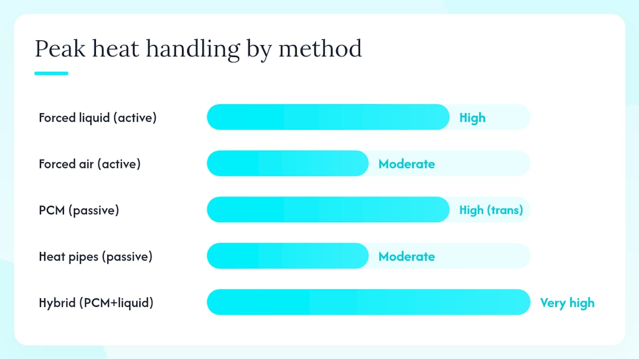
Cooling approach | Peak heat handling | Temperature uniformity | Complexity | Failure modes |
Forced liquid (active) | High | Good | High | Pump failure, leaks, freeze |
Forced air (active) | Moderate | Moderate | Low | Fan failure, dust ingress |
PCM (passive) | High (transient) | Good (transient) | Low | Saturation, phase separation |
Heat pipes (passive) | Moderate | Good | Moderate | Wick dry-out, orientation sensitivity |
Hybrid (PCM + liquid) | Very high | Excellent | High | Combined failure modes |
For active cooling design details including pump sizing and control strategies, the engineering reference covers forced liquid and air systems in depth. The decision framework for choosing between active and passive approaches is worth reviewing before committing to a cooling architecture.
Thermal barriers, spacing, and pressure relief
Cell spacing and thermal barriers between modules reduce the rate of heat transfer from a cell in runaway to its neighbors, buying time for BMS isolation and suppression systems to act. Intumescent coatings expand under heat to form insulating char layers. Ceramic fiber blankets and mica sheets are common inter-cell barrier materials. The goal is not to prevent all heat transfer indefinitely but to slow propagation enough that the pack’s other safety systems can respond.
Pressure relief paths must be designed deliberately. Vent channels should direct gas and hot ejecta away from adjacent cells, away from electrical connections, and out of the enclosure through a defined exit path. An enclosure that traps vented gas creates an explosion risk. Redundant cooling (dual pumps, bidirectional flow paths) is worth the mass penalty in high-energy stationary storage and traction applications where a cooling failure during a thermal event would be catastrophic.
Battery management systems: detection, state estimation, and mitigation
A BMS that monitors temperature alone is not adequate for high-energy packs. The case for multi-physics signal fusion is straightforward: external temperature sensors see changes after thermal propagation has already begun inside the cell. Pressure sensors, gas sensors (CO, HF precursors), and voltage anomaly detection provide earlier signals because they reflect internal electrochemical changes before surface temperature rises measurably.
Effective BMS architecture for thermal runaway prevention includes:
Multi-signal sensor fusion: temperature at multiple pack locations, cell-level voltage and current, internal pressure (where accessible), and gas sensors in the enclosure headspace
Physics-based state estimation: thermal models running in the BMS processor that estimate internal cell temperature from surface measurements and operating history, rather than relying solely on sensor readings
Kalman filter or data-driven anomaly detection: to distinguish genuine fault signatures from sensor noise and normal operating variation
Automated mitigation actions: cell isolation via contactors, module segment shutdown, forced discharge to reduce stored energy, coolant deployment, and controlled vent activation, each triggered at defined threshold combinations
Fail-safe design: the BMS must default to a safe state on processor fault, communication loss, or sensor failure, not to continued operation
Latency matters. The BMS must complete detection, decision, and actuation within a time window that keeps the pack below the point of no return for the specific cell chemistry. That window is chemistry- and format-dependent, which is why BMS validation testing must include internal short simulation, overcharge scenarios, and external heat application, with BMS response time measured against the cell’s thermal runaway onset time under each scenario.
Designers must couple thermal, electrochemical, pressure, and electrical models in the BMS state estimator. Because external sensors often see changes too late, the BMS should incorporate model-based state estimation and fusion of pressure, gas, and voltage signals for reliable lead time.
Containment and mitigation when thermal runaway starts
Even a well-designed pack will occasionally experience a cell-level event. The question is whether that event stays contained or propagates.
Passive containment relies on the physical structure: thermal insulation layers between cells and modules, intumescent coatings on cell surfaces and module walls, cell partitioning within caged structures, and fire-retardant linings on enclosure interiors. For stationary energy storage rooms, NFPA guidance on energy storage system installation specifies separation distances and construction requirements that limit propagation between rack units.
Active suppression options include water spray and water mist systems, which cool adjacent cells and slow propagation even when they cannot extinguish the electrochemical reaction inside a burning cell. Studies on suppression agent selection report that water mist can effectively cool and slow propagation during some battery fires, with certain additives enhancing performance. Novec-based agents and other clean agents are used where water damage to electronics is a concern, but their effectiveness at cooling adjacent cells is lower than water mist.
A mitigation checklist for pack designers:
Set vent activation pressure based on cell chemistry and enclosure stiffness, with sensitivity analysis around the target set-point
Route vents to a defined exit path that avoids electrical connections and personnel areas
Select suppression agent based on enclosure type, cooling priority, and environmental constraints
Design mechanical retention features to contain shrapnel from ruptured cells
Specify gas monitoring in the enclosure headspace with alarm thresholds tied to BMS actions
U.S. standards and certification pathways you need to reference
The U.S. regulatory and standards landscape for lithium-ion battery safety is not monolithic. Different standards address different aspects of the problem, and a complete certification roadmap draws from several of them.
UL 9540A is the primary test method for evaluating thermal runaway propagation in energy storage systems. It tests cell abuse, module propagation, and unit-level propagation in sequence, generating data on vent gas composition, heat release, and propagation behavior that directly informs pack acceptance criteria.
IEC 62133 covers cell-level safety testing (mechanical, electrical, and environmental abuse) and is widely referenced for cell qualification even in U.S. programs.
IEEE standards (including IEEE 1625 and IEEE 1725 for portable applications, and IEEE 2030.2 for stationary storage) address BMS performance, cell qualification, and system integration requirements.
NFPA 855 is the installation standard for stationary energy storage systems, covering separation distances, suppression requirements, and emergency response planning for facilities.
DOT/IATA regulations govern shipping of lithium cells and batteries, including state-of-charge limits, packaging requirements, and quantity restrictions for air and ground transport.
OSHA 29 CFR 1910 and OSHA’s lithium-ion battery safety guidance cover workplace hazard controls, ventilation requirements, and emergency planning for facilities that store or use lithium-ion batteries.
Building a certification roadmap means mapping each standard to the design phase where it applies. Cell qualification (IEC 62133) happens during cell selection. Pack propagation testing (UL 9540A) happens during pack design validation. Installation compliance (NFPA 855) happens during facility design. Shipping compliance (DOT/IATA) happens during logistics planning. Running these in parallel rather than sequentially compresses the program timeline without cutting corners.
NFPA’s guidance also recommends sourcing only certified batteries, maintaining continuous gas monitoring in storage locations, and limiting stored quantities, all of which should be reflected in facility design specifications.
Operational best practices: storage, charging, and maintenance
Design controls set the safety ceiling. Operations determine whether the system stays below it.
Safe storage requires temperature-controlled environments, typically 15–25°C for long-term storage, with cells held at partial state of charge (40–60% SOC) to minimize calendar aging and reduce stored energy in the event of an incident. Large battery rooms should have dedicated ventilation sized to dilute vented gases below flammable and toxic thresholds, with continuous gas monitoring tied to alarms and automatic ventilation increases.
Charging protocols matter more than most operators appreciate. Constant-current/constant-voltage (CC/CV) charging with accurate voltage cutoffs prevents overcharge. Temperature-compensated charging algorithms adjust cutoff voltage based on cell temperature, preventing the effective overcharge that occurs when a cold cell is charged to a voltage set-point calibrated for room temperature. Fast charging protocols should be validated against the cell manufacturer’s datasheet limits, not assumed to be safe because the charger hardware supports them.
Maintenance and inspection programs should include periodic electrochemical impedance spectroscopy (EIS) or DC internal resistance checks to catch cells with rising impedance before they become thermal hazards. Visual inspection cues include swelling (pouch cell expansion), electrolyte leakage, and corrosion at terminals. End-of-life replacement triggers should be defined in the maintenance SOP, not left to operator judgment.
Supply-chain controls close a gap that design reviews often miss. Sourcing cells with certified listings (UL, IEC) and maintaining lot traceability enables targeted recall actions if a manufacturing defect is identified in the field. A cell serial number database tied to pack serial numbers is the minimum traceability infrastructure for any program with warranty or liability exposure.
Emergency response for thermal runaway incidents
When a cell shows runaway symptoms, the response sequence matters as much as the suppression method.
Isolate power immediately. Open the main contactor to remove charging or load current from the affected pack. This does not stop the ongoing exothermic reaction, but it prevents electrical energy from accelerating it.
Cool adjacent cells. Apply water spray or mist to cells neighboring the affected unit to slow heat transfer and reduce the probability of propagation. Do not attempt to cool the actively venting cell directly if doing so risks exposing personnel to ejected material.
Evacuate nonessential personnel. Toxic gas generation (HF, CO, POF₃) begins before visible flames in many scenarios. The evacuation threshold should be defined in the facility emergency plan, not decided in the moment.
Notify emergency services early. Lithium-ion fires can reignite hours after apparent extinguishment. Fire departments need lead time to stage appropriate resources.
Apply suppression when safe. Water mist is the preferred agent for cooling adjacent cells and slowing propagation. Studies on extinguishing agent selection confirm water mist’s effectiveness for heat dissipation, though it does not extinguish the electrochemical reaction inside a burning cell. Specialized agents (F-500, Novec) may be appropriate depending on enclosure type and environmental constraints.
Equip responders appropriately. Self-contained breathing apparatus (SCBA) is required for anyone in the hazard zone. HF exposure risk means standard firefighting PPE is insufficient. When gas concentrations are unknown or high, specialized hazmat teams should lead entry.
Secure the scene after extinguishment. Monitor for reignition for at least 24 hours. Do not move damaged cells without appropriate containment.
Document evidence for root-cause analysis. Collect cell serial numbers, BMS event logs, charging records, and environmental data before the scene is disturbed. Photograph the pack before any disassembly. Plan destructive testing of surviving cells from the affected lot to identify whether the failure was a manufacturing defect or an operational cause.
Simulation-led validation: CFD, multi-physics modeling, and verification steps
Physics-based simulation is not a nice supplement to hardware testing. For high-energy packs, it is the primary tool for finding propagation paths before they kill a prototype or a product.
The modeling priorities for thermal runaway prevention are transient CFD of worst-case heat sources (a single cell in full runaway injecting heat into the pack structure), PCM phase-change transient modeling through saturation, and conjugate heat transfer across the full pack structure including cell-to-cell contact resistances and module housing conductivity. Each of these requires accurate material property inputs, which is where many simulation programs fail: using room-temperature thermal conductivity values for materials that change significantly at elevated temperature produces optimistic results.
Multi-physics coupling is where single-domain models consistently underpredict risk. A thermal-only model misses the pressure and gas evolution that drives vent activation timing. An electrochemical-only model misses the thermal feedback that accelerates degradation. Coupling thermal, electrochemical, pressure/gas evolution, and electrical behavior in a single simulation framework gives results that match physical abuse tests, which is the validation target.
Simulation-driven design approaches are now standard in the industry for identifying failure propagation paths before physical prototyping, shifting the design process from reactive to predictive. The multi-physics monitoring research reinforces this: because external sensors often see changes too late, model-based state estimation inside the BMS should be calibrated against the same simulation framework used for pack design.
A suggested verification workflow:
Calibrate the cell thermal model against published or measured abuse test data (nail penetration, overcharge, external heating)
Run sensitivity sweeps on vent set-points and PCM latent capacity to identify the design margins
Execute a worst-case scenario matrix: single-cell runaway in the center of the pack, corner cell, and highest-energy module
Report validation metrics: maximum cell temperature under abuse, time-to-critical temperature, vent pressure predictions, and BMS detection lead time relative to runaway onset
Pro Tip: Target PRV/vent set-points around 0.35 MPa for common cylindrical cells as a starting point in simulation, then run sensitivity analyses across your specific cell chemistry, format, and enclosure stiffness before committing to hardware. Set-points that are too low cause nuisance activation; too high risks explosive rupture.
For CFD boundary condition setup and meshing guidance specific to pack thermal simulations, the practical CFD boundary conditions reference covers turbulence model selection and thermal boundary application in detail. The heat transfer modeling guide provides the underlying conduction, convection, and radiation math for pack-level calculations.
Where design teams typically get thermal runaway prevention wrong
The most common failure pattern is not ignorance of the mechanisms. Engineers generally understand that thermal runaway is dangerous and that cell-level safeguards exist. The failure is treating those safeguards as sufficient and skipping the pack-level validation work.
A PTC thermistor that works perfectly on a single cell does nothing useful when the cell next to it is already in runaway and dumping 200W of heat into the pack structure. A CID that isolates a degraded cell is irrelevant if the BMS takes 800 milliseconds to respond and the adjacent cell reaches critical temperature in 600. The cell-level protections buy time. They do not replace the need for validated pack thermal management and a fast, multi-signal BMS.
The second failure is sequential rather than concurrent design. Cell teams, pack teams, and BMS teams that work in isolation and integrate late discover incompatibilities at the worst possible time: during propagation testing, when changing the pack structure or BMS architecture is expensive. The simulation framework should be shared across all three teams from the concept phase, with a common thermal model that cell, pack, and BMS engineers all contribute to and validate against.
Reactive reliance on vents and safety fuses is the third pattern. Vents and fuses are last-resort mechanisms. Designing a pack where the safety case depends on them activating correctly under abuse conditions is designing for failure management rather than failure prevention. The goal of a well-executed thermal runaway prevention program is that the vent never activates in service, because the BMS caught the anomaly earlier and the cooling system kept the pack within safe limits.
The Thermalysis Toolkit gives your team a simulation edge on thermal safety
The gap between a thermal safety program that passes design review and one that actually prevents propagation in hardware often comes down to simulation quality. Jewlztech’s Thermalysis Toolkit is built for exactly the validation workflow described in this guide: physics-based thermal simulation covering conduction, convection, radiation, PCM phase-change transient modeling, and pack-level conjugate heat transfer analysis.

Engineers use the Thermalysis Toolkit to run the sensitivity sweeps on vent set-points and PCM capacity that the verification workflow requires, to size coolant circuits against worst-case heat generation, and to generate the validation metrics (max cell temperature under abuse, time-to-critical temperature, BMS detection lead time) that design reviews and certification submissions need. The toolkit supports variable material properties across a wide temperature range, which matters when your simulation needs to reflect how thermal conductivity and heat capacity change during an abuse event, not just at room temperature. It is available as a downloadable Excel-based tool, so there is no infrastructure overhead to get started.
For teams building out a full thermal safety program, the EV battery thermal management guide covers pack-level design and simulation workflows in depth. Start a subscription to the Thermalysis Toolkit and run your first worst-case scenario matrix before your next design review.
Sources
The sources below are the primary references engineers should cite when justifying design controls, specifying test requirements, and building certification submissions for lithium-ion battery systems in the United States.
Recommended
Comments