
Thermal Management Solutions for Engineers: 2026 Guide
- Jewlz Technologies

- Jul 7
- 8 min read

Thermal management solutions are specialized techniques and technologies designed to regulate temperature in electronic systems, preventing overheating and extending component lifespan. Every watt of dissipated power becomes a thermal problem at sufficient density, and the consequences range from performance throttling to permanent device failure. Industries from semiconductor packaging to aerospace rely on established thermal control systems to keep junction temperatures within safe operating limits. NASA’s satellite programs and JEDEC packaging standards both treat thermal design as a first-order engineering constraint, not an afterthought.
What are the main types of thermal management solutions?
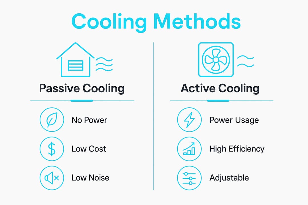
Thermal control methods split into two fundamental categories: passive and active. Passive methods require no external power input. Active methods consume power to move heat more aggressively. Choosing between them depends on heat flux, space constraints, noise tolerance, and reliability requirements.
Passive cooling methods
Passive cooling covers heat sinks, thermal interface materials (TIMs), phase-change coatings, and multilayer insulation (MLI). Heat sinks conduct heat away from a component and dissipate it through natural convection. TIMs fill microscopic air gaps between a chip and its heat spreader, dramatically reducing contact resistance. MLI blankets, standard in aerospace, use alternating reflective and insulating layers to block radiative heat transfer in vacuum environments.
Passive cooling hits physical limits in high-power applications. That limit is not a design flaw. It is a signal that the power density has outgrown what conduction and natural convection can handle alone.
Active cooling methods
Active cooling includes forced-air fans, liquid cooling loops, thermoelectric coolers (TECs), and ionic cooling modules. Fans are the most common active solution, but they consume board space and introduce vibration. Ionic cooling modules as small as 3mm enable noise-free, vibration-free thermal management in ultra-thin electronics. That form factor makes them viable where fans physically cannot fit.
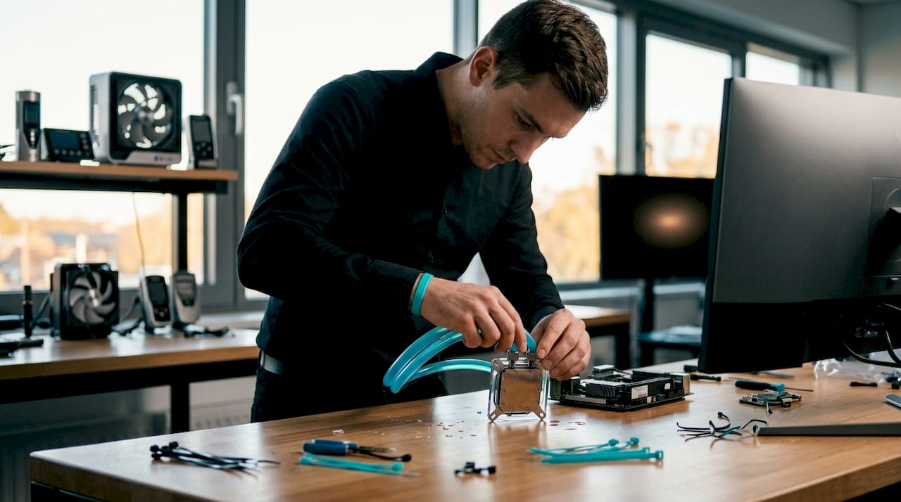
Traditional fans also constrain PCB layout. Ionic cooling frees up to 40% of board area while cooling hard-to-reach components, including what engineers call “thermal orphans,” components too far from a heat sink to benefit from it.
Pro Tip: Choose passive cooling when power dissipation stays below roughly 5W per component and acoustic noise is unacceptable. Move to active methods when junction temperatures exceed safe limits under worst-case load conditions, not average conditions.
Characteristic | Passive cooling | Active cooling |
Power consumption | None | Moderate to high |
Noise | Silent | Fan noise possible |
Complexity | Low | Moderate to high |
Heat flux capacity | Low to moderate | Moderate to very high |
Reliability | Very high | Depends on moving parts |
Best application | Low-power, space-constrained | High-density compute, precision control |
How are liquid cold plates and thermoelectric coolers shaping high-density electronics?
High-density electronics demand heat management strategies that go well beyond what air cooling can deliver. Liquid cold plates and thermoelectric coolers represent the two dominant approaches for precision thermal control in server racks, GPU clusters, and power electronics.
Liquid cold plates: single-phase vs. two-phase
Single-phase liquid cold plates circulate a liquid coolant that stays in liquid form throughout the loop. Single-phase cold plates suit moderate heat flux below 200 W/cm². That range covers most CPU and mid-range GPU applications without requiring complex phase-change infrastructure.
Two-phase cold plates allow the coolant to boil and condense within the loop, absorbing latent heat during phase change. Two-phase systems handle heat flux above 500 W/cm² with greater efficiency, reduce coolant flow rates, enable higher rack density, and operate with warm water up to 45°C. That warm-water compatibility is significant. It allows data centers to reject heat without chilled water infrastructure, cutting facility energy costs directly.
Metric | Single-phase | Two-phase |
Heat flux range | Below 200 W/cm² | Above 500 W/cm² |
Coolant flow rate | Higher | Lower |
Infrastructure complexity | Moderate | Higher |
Rack density support | Standard | High density |
Warm-water operation | Limited | Up to 45°C |
Thermoelectric coolers for precision hotspot control
Thermoelectric cooling uses the Peltier effect to pump heat from a cold side to a hot side with no moving parts. Thermoelectric cooling provides precise hotspot temperature control and is increasingly preferred over mechanical fans in critical applications. The absence of moving parts translates directly to higher mean time between failures, which matters in medical devices, aerospace electronics, and industrial control systems.
Solid-state cooling applied to GPU high-bandwidth memory (HBM) demonstrates the performance ceiling of this approach. Optimized solid-state cooling for GPU HBMs improves compute performance by 40% and yields a 5X improvement in component lifespan. The ROI case is strong: the same implementation delivers 3X return over five years and 0.15 PUE savings at the facility level.
Pro Tip: When integrating liquid cooling into an existing system, map heat flux across the board before sizing the cold plate. Oversizing flow rate does not proportionally improve thermal performance and adds unnecessary pump load and pressure drop.
What role does passive cooling play in sustainable thermal management?
Passive cooling extends well beyond electronics. At the building and urban scale, passive temperature regulation techniques reduce energy consumption and address heat island effects without mechanical systems.
Advanced passive cooling technologies reduce peak urban temperatures by up to 4.5°C, cutting reliance on mechanical air conditioning. That reduction has compounding benefits: lower grid demand, reduced carbon emissions, and improved thermal comfort in areas where air conditioning is economically or logistically unavailable.
The core passive techniques at the environmental scale include:
Radiative cooling coatings: Surfaces engineered to emit heat as infrared radiation directly to the sky, bypassing the atmosphere. These coatings can cool surfaces below ambient air temperature even under direct sunlight.
Natural ventilation design: Building orientation, window placement, and stack-effect chimneys that drive airflow without fans. Effective in climates with consistent wind patterns or significant day-to-night temperature swings.
Thermal insulation solutions: High-performance insulation materials that reduce heat ingress during peak hours, keeping interior temperatures stable without active cooling.
Evaporative and green surfaces: Vegetated roofs and walls that use evapotranspiration to lower surface temperatures, reducing radiant heat load on surrounding structures.
Passive cooling does carry real limitations. Climate dependency is the primary one. Radiative cooling loses effectiveness in humid climates where atmospheric water vapor blocks infrared emission. Natural ventilation fails in dense urban canyons with low wind speed. Engineers designing for resource-constrained or off-grid settings should treat passive methods as the first line of defense and size active systems only for the residual load that passive methods cannot handle.
What system-level design factors maximize thermal management effectiveness?
Effective heat management strategies require thinking at the system level, not just the component level. A perfectly sized cold plate fails if the facility cannot supply adequate coolant flow. A well-designed heat sink underperforms if board layout forces hot components to share airflow paths.
Liquid cooling design is a holistic choice encompassing system architecture and facility considerations, not just individual components. That framing changes how engineers approach the problem. The question is not “which cold plate fits this chip?” It is “what does the full thermal path look like from junction to coolant rejection?”
Key system-level factors to address before finalizing a thermal design:
Power density mapping: Identify the highest heat flux zones on the board and in the rack before selecting a cooling architecture. Thermal bottlenecks almost always appear at locations that were not flagged during initial layout.
Flow distribution: Uneven coolant distribution across parallel cold plates causes hot spots even when total flow rate is adequate. Use computational fluid dynamics (CFD) simulation to validate manifold designs before fabrication.
Scalability planning: A cooling architecture that works at 10 kW per rack may not scale to 50 kW without a complete redesign. Size the infrastructure for the projected peak load, not the current load.
Maintenance access: Complex liquid cooling loops with many fittings and valves increase leak risk and maintenance burden. Minimize connection points and specify dry-break couplings for serviceability.
NASA’s hybrid passive and active approach for satellite thermal control illustrates the system-level principle well. Passive methods handle baseline heat rejection during nominal mission phases. Active methods engage only during thermal extremes. That architecture minimizes power consumption while maintaining precise temperature control when it matters most.
Pro Tip: The most common thermal design mistake is validating only at nominal power. Always run thermal models at maximum TDP plus worst-case ambient temperature. Components that pass at nominal conditions often fail at the margins.
Key Takeaways
Effective thermal management requires matching the cooling method to power density, system architecture, and reliability requirements from the earliest design stage.
Point | Details |
Passive vs. active selection | Choose passive below 5W per component; move to active cooling when junction temperatures exceed safe limits under worst-case load. |
Liquid cold plate sizing | Single-phase handles below 200 W/cm²; two-phase handles above 500 W/cm² with lower flow rates and warm-water compatibility. |
Solid-state cooling ROI | Optimized solid-state cooling for GPU HBMs improves compute performance by 40% and delivers 3X ROI over five years. |
System-level design | Map power density and validate flow distribution with CFD before finalizing any liquid cooling architecture. |
Passive sustainability impact | Advanced passive cooling reduces peak urban temperatures by up to 4.5°C, cutting mechanical cooling demand at scale. |
Why software-defined thermal control is the next frontier
The thermal engineering field is shifting in a direction that most practitioners are not fully prepared for: software-defined thermal control. Hardware cooling capacity is no longer the binding constraint in many high-performance systems. The binding constraint is knowing, in real time, where heat is being generated and adjusting cooling response dynamically.
I have watched teams spend months selecting the right cold plate, only to deploy it with static flow rates that never adapt to actual workload. The hardware was right. The control logic was not. Thermal simulation tools that model transient behavior, not just steady-state conditions, are what separate good designs from great ones.
The other overlooked challenge is the gap between simulation and physical validation. CFD models are only as good as the boundary conditions engineers feed them. Inaccurate TIM conductivity values, wrong contact resistance assumptions, or simplified airflow models produce results that look credible but diverge from measured hardware. Closing that gap requires iterative validation, not a single simulation run before tape-out.
My honest recommendation: treat thermal modeling as a continuous process throughout the design cycle, not a one-time checkpoint. The engineers who do this catch problems at the schematic stage, where fixes cost hours. The engineers who skip it find problems during system integration, where fixes cost weeks.
— Joel
Jewlztech’s thermal analysis tools for engineers
Engineers who need to validate thermal designs before committing to hardware have a direct path forward with Jewlztech’s thermal analysis software.

The Thermalysis Toolkit gives engineers a purpose-built environment for thermal simulation, CFD analysis, and pressure vessel modeling. It supports the full design workflow from power density mapping through flow distribution validation, the exact steps that determine whether a cooling architecture performs as designed or fails at the margins. Jewlztech also provides free engineering software for thermal and CFD simulations, making professional-grade analysis accessible without a large software budget. Engineers can access the full suite of thermal tools directly on the Jewlztech platform.
FAQ
What are thermal management solutions?
Thermal management solutions are techniques and technologies that control temperature in electronic and mechanical systems to prevent overheating and extend component lifespan. They include passive methods like heat sinks and TIMs, and active methods like liquid cooling and thermoelectric coolers.
When should engineers use liquid cooling over air cooling?
Liquid cooling is the right choice when heat flux exceeds what air cooling can handle, typically above 100–150 W per component, or when rack density requirements make air-cooled designs impractical. Single-phase cold plates suit moderate heat flux; two-phase systems handle above 500 W/cm².
What is thermoelectric cooling and where does it work best?
Thermoelectric cooling uses the Peltier effect to move heat with no moving parts, delivering precise hotspot temperature control. It works best in applications where reliability and precision matter more than energy efficiency, such as medical devices, aerospace electronics, and laser systems.
How does passive cooling contribute to sustainability?
Advanced passive cooling technologies reduce peak urban temperatures by up to 4.5°C, directly cutting mechanical air conditioning demand. At the building and device level, passive methods lower energy consumption and extend system life by reducing thermal cycling stress.
What is the biggest mistake engineers make in thermal design?
The most common mistake is validating thermal performance only at nominal power and ambient conditions. Designs must be modeled and tested at maximum TDP combined with worst-case ambient temperature to catch failures that only appear at the margins.
Recommended
Comments