
Engineers: When to Run CFD for Jacketed Vessel Heating

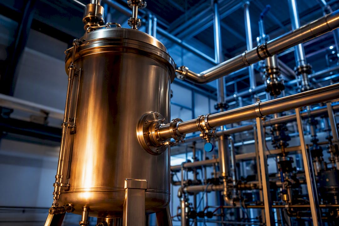
Jacketed vessel heating uses a fluid, usually steam, hot water, or thermal oil, circulated through an annular cavity around a tank to control the temperature of what’s inside. The main constraint engineers run into isn’t heat output, it’s wall conduction and thermal shock: overall U-values are often limited by the vessel wall itself (especially glass-lined units), and ramping too fast cracks linings or scorches product before you ever hit setpoint.
TL;DR:
Wall conduction limits and thermal shocks are critical constraints, especially on glass-lined vessels, affecting heating ramp speed and uniformity.
Dimple jackets improve turbulence and heat transfer while remaining lightweight, ideal for retrofit applications, but half-pipe coils excel in high-pressure, large vessels with partial coverage gaps.
Pressurized hot-water loops outperform steam in temperature uniformity, making them preferable for sensitive processes like pharmaceuticals and batch reactors.
Hand calculations suffice for simple vessels, but CFD simulations are essential for complex internals or exothermic reactions to accurately predict thermal behavior.
Proper control system design, especially cascade loops and ramp rate management, is key to avoiding cracks and uneven heating, with many failures traced back to poor control rather than hardware.
Table of Contents
How Do You Control Jacket Temperature Without Causing Thermal Shock?
What Should You Check Before Specifying a Jacketed Heating System?
Where Does Jacketed Vessel Heating Show Up Across Industries?
What Actually Separates a Good Jacketed Heating Spec From a Bad One
How Jewlztech Helps You Validate a Jacketed Heating Design Before You Build It
What Are the Main Types of Jacketed Vessel Design?
Jacket geometry determines how evenly heat spreads and how much pressure the system can handle. A conventional jacket is just a simple outer shell welded around the vessel, cheap to build but prone to uneven flow and stagnant zones at low velocity. Dimple (pillow-plate) jackets stamp a pattern of raised points into a thin outer plate, which forces turbulence into the fluid path and improves the heat-transfer coefficient over a plain conventional design while cutting weight, useful for retrofits where structural load matters.
Half-pipe coil jackets weld split-pipe channels in a spiral around the vessel, giving high velocity and pressure tolerance but leaving gaps between coils that reduce coverage. Internal coils sit inside the vessel directly in the process fluid, delivering fast response at the cost of cleanability and agitator clearance. Plate or laser-welded jackets sit between dimple and conventional in cost and performance, offering tighter channel control for viscous or sensitive products.
Conventional: low cost, uneven flow, best for simple low-duty heating
Dimple/pillow plate: higher turbulence and U-value, lightweight, good retrofit option
Half-pipe coil: high pressure rating, strong for large vessels, partial coverage gaps
Internal coils: fast thermal response, harder to clean, common in reactors
Plate/laser-welded: balanced performance, often used for sanitary or viscous service
Zoning, splitting the jacket into separate top, middle, and bottom circuits, lets you stage heating or apply differential cooling during exothermic reactions, which matters more than the jacket type itself once vessels exceed a few thousand gallons.
Which Heating Method Works Best for Your Jacket?
Steam heats fast and reaches high temperatures cheaply, but it condenses unevenly across the jacket surface, creating hot spots and requiring properly sized steam traps to clear condensate without losing live steam. Hot water solves that unevenness. Circulating hot water in a pressurized loop lets it run past 212°F without flashing to vapor, and it delivers smoother, more controllable ramps than steam because there’s no phase change disrupting the flow.
Thermal oil pushes the usable range higher still, often past 500°F, but it demands careful handling: oil degrades under prolonged overheating and poses a fire risk if a jacket weld fails. Direct steam injection (DSI) generates tempered water on demand inside a compact skid, a strong fit for facilities that don’t want a standing hot-water loop. Electric heating jackets suit smaller vessels or lab-scale work where steam or oil infrastructure doesn’t exist.
Steam: fastest ramp, cheapest infrastructure in steam-plant facilities, uneven heating risk
Hot water: best control fidelity, gentle ramps, needs pressurization above 212°F
Thermal oil: highest temperature ceiling, added safety and handling burden
DSI: compact, on-demand hot water, good for retrofit
Electric: simple, low-maintenance, limited to smaller duty
Pressurized hot-water loops consistently outperform steam on temperature uniformity, which is why many process engineers specify packaged hot-water TCUs for anything sensitive to hot spots, batch reactors, coatings, or pharmaceutical intermediates chief among them.
How Do You Calculate Heat Transfer in a Jacketed Vessel?
The overall heat-transfer coefficient, U, combines the resistances of the jacket-side film, the vessel wall, and the process-side film in series. For most steel vessels, the process-side film dominates, but for glass-lined reactors the glass lining itself becomes the bottleneck because glass conducts heat poorly compared to steel. That single fact changes how you spec the whole system, since no amount of jacket-side flow will compensate for a low-conductivity wall.
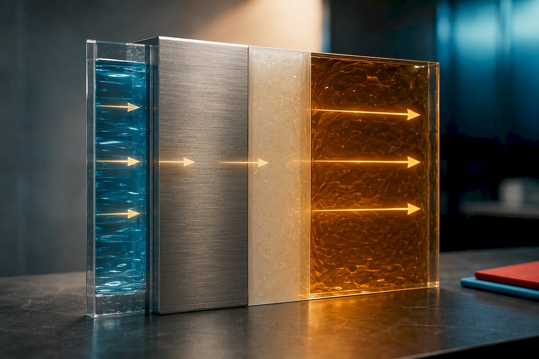
Log-mean temperature difference (LMTD) estimates the driving force between jacket and process fluid, but it assumes steady-state conditions, which rarely hold true during batch heat-up or cool-down. For transient behavior, you need a time-stepped model rather than a single LMTD snapshot.
A basic hand-calculation walkthrough looks like this:
Gather jacket fluid inlet/outlet temperatures, flow rate, and vessel wall material and thickness.
Estimate jacket-side and process-side film coefficients from correlations or vendor data.
Combine resistances into an overall U, checking published U-value ranges for your jacket and wall type.
Calculate LMTD from the four terminal temperatures.
Multiply U, surface area, and LMTD to get instantaneous heat duty, then integrate over the batch if temperatures shift significantly.
Pro Tip: If your vessel is glass-lined, budget for a U-value well below what a bare steel wall would give you. Plan on slower ramp rates or added surface area rather than assuming higher jacket flow will fix the gap.
How Do You Control Jacket Temperature Without Causing Thermal Shock?
Temperature control units (TCUs) manage the loop between the heat source and the jacket, using electric heaters, steam-to-water exchangers, or glycol chillers depending on whether the process needs heating, cooling, or both in sequence. Most modern TCUs run a cascade control loop: an outer PID watches process fluid temperature, while an inner PID adjusts jacket supply temperature faster than the process can respond, smoothing out overshoot.
Thermal shock is the real threat, especially on glass-lined reactors, where a sudden temperature swing can crack the lining outright. Ramping gradually and letting automated cascade loops manage ΔT rather than manual valve adjustments protects both the vessel and the batch.
Limit ΔT between jacket and process fluid during ramp-up, particularly on lined vessels
Purge steam lines before startup to clear air and prevent water hammer
Size condensate pumps and steam traps for peak load, not average load
Inspect trap function regularly; a failed trap silently kills heating capacity
Pro Tip: A cascade loop with a fast inner loop and slow outer loop almost always beats a single PID for batch heat-up, because it reacts to jacket temperature before the bulk fluid even starts moving.
What Should You Check Before Specifying a Jacketed Heating System?
Matching pressure and temperature ratings to jacket type comes first. A half-pipe coil handles higher jacket-side pressure than a conventional jacket of the same wall thickness, which matters when your heating medium runs above 100 psi. National Board and ASME pressure vessel standards govern the allowable working pressure for each jacket configuration, so the rating drives the geometry choice, not the other way around.
Confirm process viscosity and agitation needs; thick or shear-sensitive fluids may need dedicated rheology and mixing guidance to avoid localized overheating near the wall.
Size coil or jacket flow to the heat duty, not just the vessel volume.
Plan zoning and piping layout so pressure drop stays manageable across long coil runs.
Specify insulation thickness and, for extreme service, a vacuum jacket option.
Verify material compatibility and sanitary finish requirements for the process fluid.
Getting these five right up front avoids the expensive fix of re-piping a jacket after commissioning.
When Should You Simulate Instead of Calculate by Hand?
Hand calculations assume uniform flow and steady state, assumptions that break down fast in vessels with complex internals, strong exotherms, or coils competing with an agitator for flow path. That’s when CFD studies on coil placement become worth running: coil position alone has been shown to shift thermal efficiency by a factor of 2 to 3 in complex tank geometries, a gap no hand calculation catches.
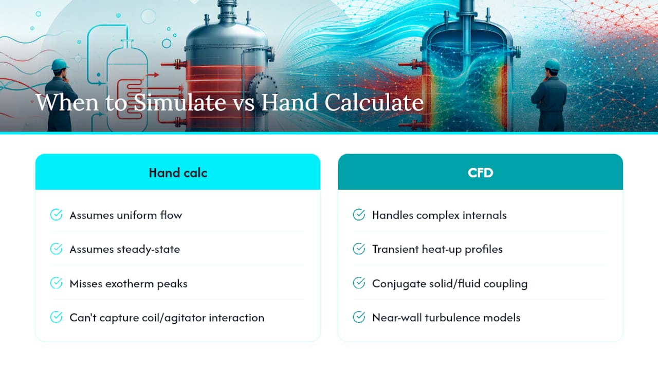
Good simulation setups couple solid and fluid domains (conjugate heat transfer), run transient rather than steady-state for heat-up profiles, and typically lean on a near-wall capable turbulence model for jacket-side flow. Jewlztech’s own CFD heat transfer and conjugate heat transfer guides walk through boundary condition setup for exactly this case, and the Cryogenic Pressure Vessel & Boil-Off Simulator shows the same modeling approach applied to extreme low-temperature service.
Pro Tip: Run a transient model for any batch process where the exotherm peak matters more than the average heat duty. A steady-state U calculation will miss the overshoot entirely.
Where Does Jacketed Vessel Heating Show Up Across Industries?
Pharma and biotech vessels demand sanitary finishes, validated temperature bands, and tight documentation, often narrowing jacket choice to plate or dimple designs that clean easily. Food and beverage processing adds CIP cycles and viscosity swings mid-batch into the mix. Chemical processing brings exothermic reactions and corrosion resistance to the front of the spec sheet, frequently pushing designers toward half-pipe coils rated for aggressive cooling flow. Marine and cargo tank heating runs on a different clock entirely, long-duration, energy-efficiency-driven heating where coil placement inside oddly shaped tanks becomes a major design variable.
Pharma/biotech: sanitary finish, validation, narrow ΔT tolerance
Food/beverage: CIP compatibility, variable viscosity
Chemical: exotherm management, corrosion-resistant materials
Marine/cargo: long-duration heating, coil geometry drives efficiency
What Actually Separates a Good Jacketed Heating Spec From a Bad One
Most failures I’ve seen traced back to control, not hardware. Engineers spend hours picking jacket geometry and barely touch the ramp profile, then wonder why the glass-lined reactor cracked on batch three. Prioritize the cascade loop and the ramp rate before you argue about half-pipe versus dimple. Match jacket type to actual pressure and duty, not habit. And when geometry gets weird or the exotherm is real, stop hand-calculating and run the transient model. The math on paper lies about dead zones; the simulation doesn’t.
— Joel
How Jewlztech Helps You Validate a Jacketed Heating Design Before You Build It
Hand calculations get you a starting U-value. They don’t tell you what happens when a coil sits too close to the agitator shaft, or how fast a glass-lined wall actually ramps once you factor in real transient behavior. Jewlztech’s thermal analysis toolkit covers conduction, convection, and radiation modeling with a built-in material property database, so you’re not rebuilding property tables for every wall thickness or fluid combination.

For the geometry problems where coil placement or jacket zoning genuinely change the outcome, the CFD simulation software models flow and temperature fields directly instead of assuming uniform mixing. If your process runs at the extreme end of the temperature range, the engineering toolkit supports that too. Try the free tools first on your next jacket sizing problem, then request a demo if you need transient or CFD-backed analysis on a real vessel.
Sources
Recommended
Comments