
Enclosure Heat Dissipation: When 5 W per L Means CFD for Engineers

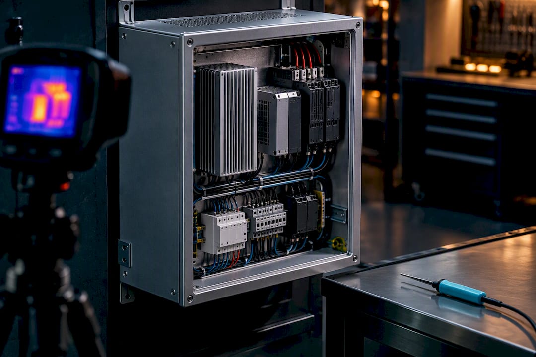
For most electrical enclosures, passive conduction and radiation handle loads under roughly 2 to 3 watts per square foot; above that, you need internal circulation, and once density climbs past about 5 watts per liter or the ambient runs hot and sunlit, a closed-loop exchanger or air conditioner is the right call. Before picking hardware, calculate the enclosure’s surface area and total internal watts, convert to watts per square foot, and estimate the temperature rise. That number, checked against IEC TR 60890 guidance and a reasonable safety margin, tells you whether you’re done or whether you need a fan, an exchanger, or a CFD run.
TL;DR:
Enclosures dissipate heat primarily through conduction, convection, and radiation, requiring active cooling beyond 2 to 3 watts per square foot or 5 watts per liter.
To size cooling correctly, sum worst-case internal wattage, measure exposed surface area, calculate watts per square foot, and compare to manufacturer curves or IEC guidelines.
The decision between sealed and vented enclosures depends on contamination risk and internal heat density, with sealed enclosures suited for dusty or corrosive environments.
Internal circulation fans can significantly improve cooling efficiency at a lower cost and should be used when internal heat exceeds about 5 W per liter or ambient surpasses 40°C.
CFD modeling is recommended when internal geometry is complex, crowded, or when hotspots need precise validation beyond simple hand calculations.
Table of Contents
How Do You Calculate Enclosure Heat Dissipation?
Start with the surface area that actually radiates or convects heat to ambient. For a wall-mounted enclosure, that means excluding the back panel and any face bolted flush to a wall or panel, since those surfaces can’t shed heat outward. The standard approach, drawn from manufacturer sealed-enclosure guidance, sums the exposed faces of the box in square feet.
Next, build a loss inventory. Pull watt ratings from every component datasheet, VFDs, transformers, PLCs, power supplies, resistive loads, and add them up using worst-case figures, not typical or best-case numbers. Optimistic loss estimates are the single most common reason enclosure cooling calculations fail in the field.
Once you have total watts and total exposed square feet, divide one by the other to get watts per square foot. Manufacturers such as nVent/Hoffman publish sealed-enclosure curves that convert that figure directly into an expected internal temperature rise above ambient.
Worked example:
Step | Value |
Enclosure dimensions | wall-mounted |
Exposed surface area | exposed surface area |
Total internal losses (worst-case) | total internal losses |
Watts per square foot | loading figure |
Estimated temperature rise (sealed curve) | ~35–40°F above ambient |
Measure every exposed face and sum the area, dropping the mounted back panel.
Total the worst-case wattage of every internal component.
Divide watts by square feet to get the loading figure.
Read the expected ΔT off the manufacturer’s sealed-enclosure chart or the IEC TR 60890 temperature-rise method.
If active cooling is needed, size fan CFM. A fan airflow in cubic feet per minute (CFM) can be estimated by dividing the product of 3.16 and watts by the temperature rise in °F, or convert watts to BTU/hr (1 W ≈ 3.41 BTU/hr) for exchanger and AC sizing.
If that 35 to 40 degree rise pushes internal air above your hottest component’s rated ambient, you’ve already found your answer: this box needs help beyond sealed conduction and radiation.
Which Heat-Transfer Modes Matter Inside an Enclosure?
Three physical mechanisms move heat inside any cabinet, and a credible model accounts for whichever ones are actually active rather than defaulting to airflow as if it explains everything. Conduction carries heat through metal walls, mounting brackets, and DIN rails to the points where it can leave the box. Convection, natural or forced, moves warmed air past internal surfaces and out through the enclosure skin. Radiation transfers heat between hot components and cooler enclosure walls even when there’s no airflow at all, and it’s often underestimated in dense, low-airflow boxes.
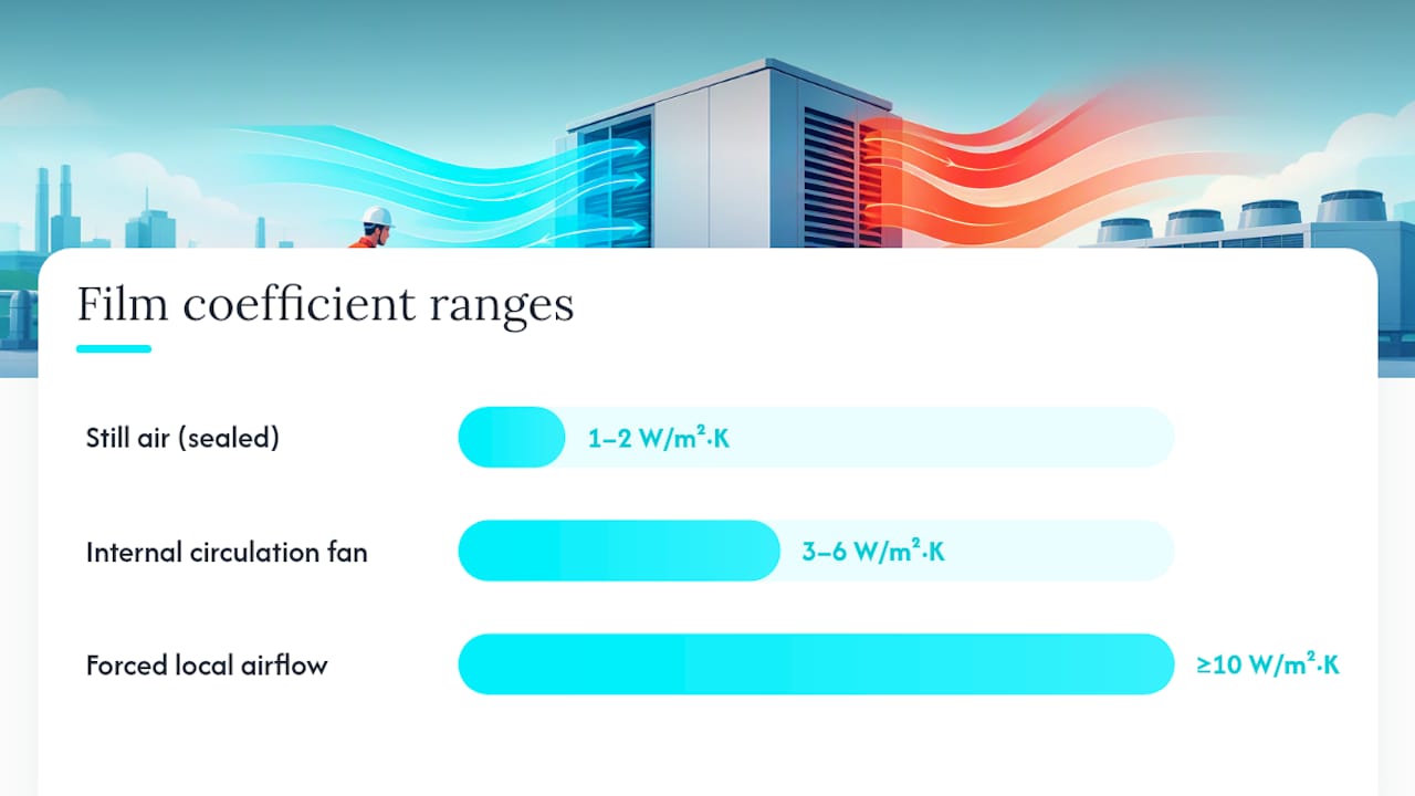
Practical film-coefficient ranges you can use to sanity-check hand calculations:
Still air (natural convection, sealed box): roughly 1 to 2 W/m²·K
Internal circulation fan running: roughly 3 to 6 W/m²·K
Forced local airflow across a component: 10 W/m²·K or higher
These ranges shift with geometry. Enclosures crowded with internal objects or unusual aspect ratios can produce Nusselt numbers well outside generic flat-plate correlations, which is one reason simple hand calculations sometimes miss hotspots that CFD modeling catches.
Sealed vs. Ventilated: Which Enclosure Type Fits Your Load?
The decision usually comes down to contamination risk and internal heat density, not preference. Sealed enclosures (IP65/IP66 or NEMA 4/4X) keep dust, washdown water, and corrosive atmospheres out, but they force you to rely on conduction and radiation through the enclosure skin, plus whatever active cooling you add inside. Ventilated enclosures let outside air do the work through louvers or filtered fans, which dissipates far more heat per square foot but exposes internals to whatever is in that air.
Several physical and environmental factors shift where that line falls:
Material and finish: painted or powder-coated steel radiates heat more efficiently than unfinished aluminum or stainless steel, which reflect more infrared and dissipate less by radiation.
Surface area and mounting: wall-mounted, back-to-wall, or side-by-side ganged enclosures lose usable radiating area; subtract those faces before running the W/ft² calculation.
Solar load: direct sun on an outdoor cabinet adds heat the loss inventory won’t capture unless you measure or estimate it separately.
Altitude and high ambient: thinner air at elevation reduces convective cooling efficiency, and manufacturer application notes call for de-rating fan and exchanger capacity accordingly.
IP rating and contamination risk: a washdown environment or abrasive dust load usually forces a sealed enclosure even when a vented design would dissipate heat more easily.
Statistic callout: Solar shields mounted above outdoor enclosures can cut solar-induced internal temperature rise by roughly 25 to 46 percent in manufacturer testing, which often means the difference between needing a full air conditioner and getting by with a closed-loop exchanger.
What Cooling Option Should You Choose, and How Do You Size It?
Pick the least aggressive option that clears your calculated ΔT with margin, then size it with formulas instead of guesswork. Internal equalization fans are the cheapest fix and the most underused: they don’t remove heat from the box, they just eliminate air stratification so every wall participates in radiating and conducting heat outward. Moving internal air at 1 to 2 m/s can raise effective cooling area by a factor of roughly 3 to 4 compared with dead-air convection, which frequently resolves a localized hotspot without breaking the seal.
For ventilated enclosures, size the exhaust fan with:
A fan airflow in cubic feet per minute (CFM) can be estimated by dividing the product of 3.16 and watts by the temperature rise in °F
A 200 W load with a 20°F allowable rise needs roughly 32 CFM. Mount the fan as an outlet high on the enclosure with a filtered inlet low and opposite, so air sweeps across hot components instead of short-circuiting near the top. Small rack-mount fan panels, like this 1U dual-fan unit, illustrate the scale of airflow typically needed for a single rack slot.
Calculate total watts and target ΔT.
Run the CFM formula for a vented design, or check the closed-loop exchanger’s rated capacity in watts against your loss inventory for a sealed one.
Escalate to a closed-loop exchanger or air conditioner once internal dissipation exceeds roughly 5 W per liter of enclosure volume, or ambient routinely runs above 40°C.
Budget for filter maintenance on any vented or exchanger design; clogged filters are a leading cause of field failures.
Heat pipes are worth considering for vibration-heavy environments, since they move heat passively with no moving parts to fatigue or clog.
Pro Tip: Don’t oversize the exchanger just because the math is close. A slightly undersized fan solution with a documented safety margin is usually cheaper to maintain than an oversized AC unit that short-cycles and accumulates condensate.
How Do You Verify a Heat Dissipation Design Before It Ships?
Verification starts with the same worst-case loss inventory used for sizing, checked against IEC TR 60890 or the simplified evaluation methods in IEC 62610. A design that passes on optimistic losses hasn’t been verified at all.
Confirm the hottest component’s junction or case temperature against its datasheet rating, not just the average internal air temperature.
Check cable and terminal ratings against the calculated internal ambient, since insulation de-rates with heat too.
Apply a safety margin on chart-based estimates. Manufacturer guidance commonly recommends around 25 percent on top of the calculated cooling requirement.
De-rate for altitude and high ambient using the equipment manufacturer’s published curves.
Test fault scenarios explicitly: blocked filter, failed fan, and peak solar load, and define a pass/fail threshold for each before you build the prototype.
When Should You Move From Hand Calculations to CFD?
A hand calculation and a sealed-enclosure chart cover most sizing decisions in a few minutes. Reach for CFD when internal geometry gets crowded, when component placement creates recirculation zones a flat-plate coefficient can’t represent, or when you need to prove a specific hotspot stays under limit rather than just the average internal temperature.
Loss inventory → hand calculation → baseline cooling selection → CFD for hotspot validation → iterate.
Use calculators for straightforward vented or sealed boxes with evenly distributed loads.
Use CFD when internal objects, unusual aspect ratios, or high Rayleigh-number regions make simple correlations unreliable.
The Jewlz Engineering Toolkit covers conduction, convection, and radiation calculations alongside CFD and pressure-vessel simulation, with a built-in material property database, so a baseline hand calculation and a full simulation run can happen in the same workflow.
What Field Mistakes Should You Watch For?
Most enclosure cooling failures I’ve seen traced back to two things: an optimistic loss inventory and skipping the hottest-component check because the average air temperature looked fine. Write down your assumptions and test results. The next revision will thank you.
— Joel
Ready to Move From Hand Calculations to Simulation?
A spreadsheet gets you a defensible sealed-enclosure estimate in ten minutes. When you need to prove a specific hotspot stays under limit, or your geometry has internal objects that break flat-plate assumptions, that’s where the Jewlz Engineering Toolkit picks up. It combines conduction, convection, and radiation analysis with CFD and pressure-vessel simulation in one downloadable, Excel-based tool, with a built-in property database so you’re not hunting for material data mid-calculation.

Some tools offer free basic features without requiring a license, which makes them a practical first stop for students and small teams who need engineering-grade numbers without a procurement cycle. If your enclosure design has cleared the hand calculation but you’re not confident in the hotspot, run a baseline case through the engineering toolkit and see where the model disagrees with your assumptions. That disagreement is usually where the real design work starts.
Sources
For formal verification, consult IEC TR 60890 and IEC 62610; for chart-based selection, use nVent/Hoffman’s sealed-enclosure spec.
FAQ
How Do I Calculate Heat Dissipation in an Enclosure?
Sum the worst-case wattage of every internal component, then divide by the exposed surface area in square feet to get watts per square foot. Match that figure against a sealed-enclosure curve or the IEC TR 60890 method to estimate the internal temperature rise.
How Much Heat Does a Server Rack Dissipate?
It depends entirely on the installed hardware. Rack heat load has no fixed figure; you calculate it the same way as any enclosure, by totaling the rated watts of every server, switch, and power supply installed, then applying the CFM or exchanger sizing formulas to that total.
What Are the Three Main Methods of Heat Dissipation?
Conduction, convection, and radiation are the three physical mechanisms that move heat, and any credible enclosure model needs to reflect the modes that are actually active in that specific design. Sealed enclosures often rely mostly on conduction and radiation, while vented designs lean on forced convection.
How Do I Choose Between a Sealed and Ventilated Enclosure?
Choose sealed when dust, moisture, or corrosive atmosphere pose a real contamination risk, and choose ventilated when the environment is clean and you need higher heat dissipation per square foot. Once a sealed design’s internal density passes roughly 5 watts per liter, a closed-loop exchanger usually becomes necessary regardless of ambient conditions.
When Do I Need CFD Instead of a Hand Calculation?
Hand calculations work well for evenly loaded boxes with simple geometry, but crowded internal layouts or unusual aspect ratios can produce airflow patterns that flat-plate coefficients don’t capture. The Jewlz Engineering Toolkit lets you run a baseline hand calculation and escalate to full CFD without switching platforms.
Recommended
Comments