
Cut Condenser Length 44%: Condensation Heat Transfer for Engineers


Condensation heat transfer is the latent-heat-driven exchange that occurs when vapor contacts a surface below its saturation temperature, releasing energy as it changes phase into liquid. Filmwise condensation dominates most industrial surfaces and follows well-established Nusselt-based correlations, while dropwise condensation can move several times more heat but rarely persists on its own. The practical implication for engineers is straightforward: mode, geometry, vapor quality, and noncondensable gas content set the local heat-transfer coefficient, and enhancement pays off most where thermal resistance in the condensate film is highest.
TL;DR:
Condensation heat transfer efficiency drops significantly at low vapor quality and in the presence of noncondensable gases, especially near the condenser exit.
Surface treatments like lubricant-infused coatings can promote dropwise condensation, but their durability and fouling resistance limit long-term industrial effectiveness.
Mechanical enhancements such as microfin tubes are more robust, often doubling heat transfer rates, but they can cause increased pressure drops and manufacturing costs.
Using a performance evaluation criterion to localize enhancement efforts in the poorest thermal resistance zones optimizes system benefits relative to pressure-drop penalties.
Table of Contents
How Does Condensation Heat Transfer Work? Fundamentals and Governing Equations
Which Correlations Are Validated, and How Much Uncertainty Should You Budget?
How Should Engineers Approach CFD and Conjugate Heat Transfer Modeling?
Where Does Condensation Heat Transfer Matter Most in Practice?
Condenser Design Checklist: A Quick-Reference Best Practices List
How Does Condensation Heat Transfer Work? Fundamentals and Governing Equations
Every condenser design starts with one of two physical pictures: a continuous liquid film or a population of discrete droplets. Filmwise condensation forms when the condensate wets the surface completely, building a thin liquid layer that vapor must diffuse through before it can reach the cold wall and release its latent heat. That film is the bottleneck. Nusselt’s classic film theory, developed for laminar flow on a vertical plate, assumes negligible inertia and convection terms in the liquid film, a linear temperature profile across the film thickness, and a smooth vapor-liquid interface. From those assumptions comes the local heat-transfer coefficient as a function of film thickness, which itself grows with distance down the plate as more condensate accumulates.
Dropwise condensation is the opposite picture. Instead of a continuous film, condensate nucleates as discrete droplets that grow, coalesce, and then depart the surface under gravity or shear, continually exposing fresh, thermally resistant-free area to incoming vapor. Because the film’s conduction resistance is what limits filmwise heat transfer, removing that film mechanically through droplet shedding is why dropwise condensation heat-transfer coefficients can run several times higher than filmwise values on the same surface. The catch is that dropwise behavior requires a nonwetting surface, and most industrial fluids and untreated metals default to filmwise wetting.
For calculations, a handful of correlation families cover most engineering situations:
Nusselt film theory for laminar, gravity-drained films on vertical plates and horizontal tubes, still the reference case for hand calculations and quick sizing checks.
Horizontal tube bank correlations that account for condensate inundation from tubes above, which thickens the film on lower rows and reduces their local coefficient.
In-tube condensation correlations in the Akers family and its descendants, built for annular and stratified flow regimes inside horizontal and vertical tubes, common in refrigeration and HVAC&R condensers.
Two-phase flow pattern maps that determine whether a correlation built for annular flow even applies, since stratified or wavy-annular regimes change the dominant heat-transfer mechanism.
Correlations remain the right tool when the geometry is simple, the flow regime is known, and you need a fast design estimate or a sanity check on a numerical model. Reach for a numerical or CFD-based model when geometry is complex (finned tubes, plate-fin exchangers, mixed convective and phase-change regions), when noncondensable gases create spatial concentration gradients that a lumped correlation cannot capture, or when you need local, not just average, heat-transfer coefficients to locate hot spots or condensate flooding risk.
What Effect Do Vapor Quality and Noncondensable Gases Have?
Vapor quality, the mass fraction of vapor in a two-phase mixture, is not a side detail. It governs which flow regime you are in and how much liquid film thickness the vapor has to push through. As quality drops toward the exit of a condenser, more liquid accumulates, films thicken, and the local heat-transfer coefficient falls even as the mass flux may stay roughly constant. Low-quality regions are almost always the performance bottleneck in a real condenser, which is exactly why enhancement techniques concentrated there tend to produce the largest system-level gains.
Noncondensable gases (NCGs) compound the problem in a different way. Air or other NCGs mixed into a condensing vapor stream do not condense, so they accumulate near the liquid-vapor interface as the condensable vapor is depleted there. That buildup creates a diffusion resistance layer the incoming vapor molecules must cross before they can reach the cooler surface, and experimental work on vertical plates and horizontal tubes confirms this significantly decreases both the heat-transfer coefficient and condensation mass flux compared to a pure-vapor case at the same conditions. Even a few percent NCG by mass can produce a measurable coefficient drop, and the effect worsens as the mixture becomes more dilute in condensable vapor toward the end of the condensing path.
Practical indicators that NCG is degrading your condenser include:
A measured overall heat-transfer coefficient noticeably below the pure-vapor design value at the same flow and temperature conditions.
Temperature profiles along the condenser that flatten out or plateau earlier than the design curve predicts.
Persistent subcooling or a wider than expected approach temperature at the vent or air-removal point.
Mitigation is mostly about removal and layout: dedicated vent lines placed where NCG is expected to concentrate, air ejectors or vacuum pumps sized for the actual leak-in rate rather than a nominal estimate, and orienting flow so NCG is swept toward the vent rather than trapped in a stagnant pocket.
Which Correlations Are Validated, and How Much Uncertainty Should You Budget?
Choosing a correlation is a matter of matching geometry, reduced pressure, and mass flux to the range the correlation was actually validated against, not just picking the most cited formula. Semi-empirical correlations built for vertical plates and horizontal tubes are the most extensively validated cases in the literature.
Statistic to plan around: Semi-empirical correlations for condensation mass flux on vertical plates and horizontal tubes have been shown to match experimental measurements within roughly ±3% to ±6% for the geometries and conditions those studies covered. That is a tight enough margin to use directly in a design safety factor for those specific configurations, but it does not automatically transfer to different geometries or flow regimes.
The gap between geometry-specific correlations and broader, cross-study models matters here. Work that pools condensation heat-transfer and pressure-drop datasets across wide reduced-pressure ranges, drawing on datasets with more than a thousand heat-transfer data points, reports mean deviations closer to ±22.6% for the aggregated heat-transfer model. The lesson is not that one model is bad and the other good. It is that uncertainty tightens dramatically when a correlation is matched to a narrow, well-characterized operating window, and widens fast the moment you extrapolate outside that window.
When selecting a correlation for a real project:
Check the reduced pressure range the correlation was fit against and confirm your operating point sits well inside it, not near the boundary.
Match mass flux and flow regime (stratified, wavy, annular, mist) to the correlation’s stated applicability, since a formula built for annular flow will mislead you in stratified conditions.
Favor geometry-matched correlations (plate versus horizontal tube versus in-tube) over generalized cross-study models whenever your design falls inside the geometry-specific dataset’s range.
Add margin proportional to how far your conditions sit from the correlation’s validated envelope, not a flat safety factor applied uniformly.
How Do Engineers Measure and Validate Condensation Data?
Every correlation and every CFD model ultimately traces back to a physical experiment, and the quality of that experiment sets a ceiling on how much you should trust the number downstream. Most plate and tube condensation studies use one of two rigs: a cooled vertical plate or tube section with embedded thermocouples measuring wall temperature at multiple axial positions, or a shell-and-tube style test section with condensate collection for direct mass-flux measurement. Vapor-side conditions, pressure, temperature, and NCG concentration, get measured upstream and downstream to bound what the vapor actually looked like at the test surface, not just at the inlet manifold.
Three things tend to distort reported coefficients if you are not careful reading a paper:
Wall temperature measurement location matters more than it seems. Thermocouples embedded slightly below the actual condensing surface introduce a conduction correction that, if done poorly, inflates or deflates the inferred coefficient.
Uncontrolled NCG ingress during testing, even trace air leaking into a nominally pure-vapor loop, can quietly shift results toward lower coefficients without the researchers realizing the gas fraction changed mid-test.
Condensate subcooling at the collection point skews mass-flux-based heat-transfer calculations if the energy balance does not account for sensible heat picked up after the phase change itself.
When you validate a simulation against published data, match the boundary conditions exactly, including NCG fraction, subcooling, and orientation, before comparing coefficients. A CFD result that looks 15% off from a correlation might simply be solving a slightly different problem.
Pro Tip: Before trusting a published condensation dataset for design work, check whether the paper reports an energy balance closure (inlet vapor energy versus condensate plus outlet vapor energy). A closure within a few percent is a decent proxy for how carefully the experiment controlled for NCG leakage and subcooling errors.
Which Condensation Enhancement Techniques Actually Work?
Enhancement strategies fall into three broad categories, and picking the right one depends heavily on where in the condenser you are trying to intervene and what you are willing to trade off.
Surface engineering changes wetting behavior at the microscale to push filmwise condensation toward dropwise-like performance. Superhydrophobic coatings, hydrophobic-hydrophilic patterned surfaces, and lubricant-infused surfaces all fall in this bucket. Lubricant-infused surfaces in particular have shown, in controlled steam condensation experiments, dropwise-like droplet behavior and improved heat transfer relative to untreated filmwise surfaces under the tested conditions. The mechanism is straightforward: a nonwetting or lubricant-coated surface prevents the condensate from spreading into a continuous film, so droplets nucleate, grow, and shed before they can build the conduction resistance a film would.
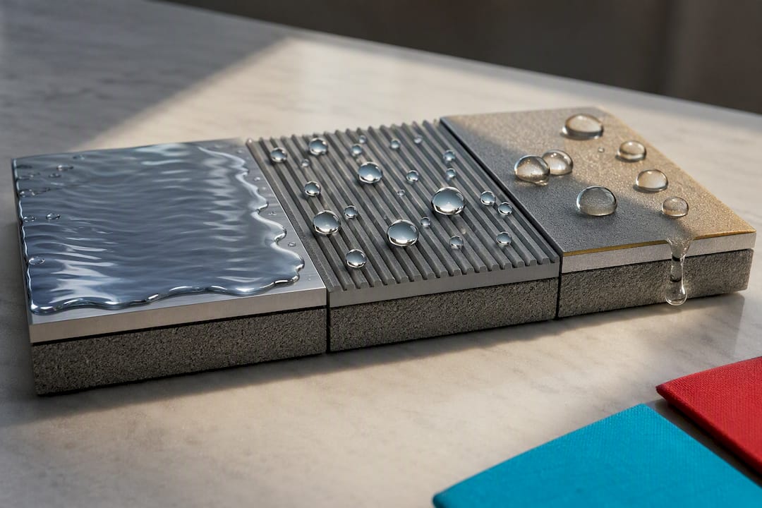
Statistic worth flagging: engineered nano and micro-structured surfaces can meaningfully increase condensation heat transfer by controlling droplet distribution and departure size, but the durability and fouling trade-offs are real constraints in long-running industrial service. Coatings degrade, lubricant layers deplete, and scaling or particulate fouling can defeat the surface chemistry that made dropwise behavior possible in the first place. Treat any surface-engineering gain reported in a lab study as an upper bound, not a guaranteed field number.
Geometry changes are the more mechanically robust option. Microfin tubes, knurled surfaces, and grooved tubes increase effective surface area and disrupt the condensate film, and some experimental configurations report heat-transfer coefficient increases of more than double relative to a smooth tube, with the gain scaling with groove depth and decreasing pitch. Because these are passive, machined features rather than a coating, they tend to hold up better over years of service, though they do add manufacturing cost and, in finned configurations, can increase pressure drop on the vapor side.
Active methods intervene dynamically rather than through fixed geometry or surface chemistry:
Electrohydrodynamic (EHD) enhancement uses electric fields to destabilize the condensate film and promote droplet shedding, most effective in low-quality regions where film thickness is already the dominant resistance.
Acoustic excitation vibrates the surface or fluid to disrupt film buildup, and design-guideline literature suggests that combining acoustic methods with microfin tube geometry can reduce required condenser tube length by up to roughly 44% in some studied configurations, largely because the combined effect targets the same low-quality bottleneck from two directions at once.
Active methods tend to outperform purely geometric solutions specifically in low-quality zones, where film thickness dominates and mechanical disruption has the most resistance to remove. They come with added system complexity, power draw, and maintenance requirements that a passive groove or coating does not carry, so the decision is rarely “which technique is best” in the abstract. It is which technique fits the specific resistance bottleneck, pressure-drop budget, and maintenance capacity of the system you are actually designing.
How Should You Design Condensers Around These Trade-Offs?
The single most useful design concept for allocating enhancement effort is the performance evaluation criterion, or PEC: a framework that weighs the heat-transfer gain from an enhancement against the pressure-drop penalty it introduces, usually normalized against pumping power or fan power cost. An enhancement that doubles the local heat-transfer coefficient but triples pressure drop across that section may fail a PEC test even though the raw heat-transfer number looks impressive on a spec sheet. Running a PEC calculation before committing to a surface treatment or geometry change is the difference between an enhancement that helps the whole system and one that just moves the bottleneck somewhere else, like the fan or pump.
Design-guideline literature converges on a specific recommendation here: localize enhancement to the regions of maximum condensate thermal resistance, which in most condensers means the low vapor quality zones near the exit rather than the high-quality inlet region. Applying an expensive coating or active method uniformly across a condenser wastes effort on sections where the coupling-fluid-side resistance, not the condensate film, is already the limiting factor. The exceptions worth flagging:
Temperature pinching near the condenser exit can shift where the true bottleneck sits, since a tight approach temperature at the cold end sometimes makes that zone more sensitive to enhancement than a quality-based analysis alone would suggest.
Air-coupled condensers (finned-tube, air-cooled) usually have their dominant resistance on the air side, not the condensate side, so investing in surface engineering on the condensing surface delivers far less system benefit than improving air-side fin design or airflow.
Liquid-coupled condensers (shell-and-tube with water or refrigerant on the coupling side) more often have condensate-side resistance as the true limiter, which is where microfin, EHD, or surface treatments earn their keep.
Retrofit projects face a narrower set of realistic options than new-build designs. You cannot usually change base tube diameter or overall shell geometry on an existing unit, so retrofit enhancement tends to lean on surface treatments, insertable tabulators, or acoustic add-ons rather than a full geometry redesign. New-design projects have the freedom to select microfin or grooved tube geometry from the outset, which is usually the more durable long-term investment when the budget allows for it. A tool built for heat exchanger optimization can help quantify these PEC trade-offs before committing to hardware.
How Should Engineers Approach CFD and Conjugate Heat Transfer Modeling?
Reach for CFD or conjugate heat transfer modeling when correlations cannot capture what you need: complex finned geometry, spatially varying NCG concentration, or local hot-spot identification rather than a single average coefficient. If a vertical plate or horizontal tube correlation already covers your geometry and operating range within an acceptable uncertainty band, a full CFD run is often more effort than the design question warrants.
When you do build a condensation model, a few solver decisions matter more than mesh count alone:
Interface treatment determines whether the model resolves the liquid film directly (interface-tracking or volume-of-fluid approaches) or uses a wall-film model that approximates film thickness without fully resolving it, a choice that trades accuracy for computational cost.
NCG treatment should solve an explicit species transport equation for the noncondensable gas rather than lumping it into a single-phase approximation, since concentration gradients near the interface are exactly what drives the diffusion resistance that degrades performance.
Turbulence model selection in the vapor phase affects predicted shear on the condensate film, which in turn affects film thickness and local coefficient, particularly in annular in-tube flow.
Mesh resolution near the wall needs to be fine enough to resolve the thermal boundary layer in the condensate film itself, not just the bulk vapor flow, or the model will underpredict the conduction resistance that dominates filmwise condensation.
Validation should follow a consistent workflow: run a mesh and time-step sensitivity study first, then compare predicted coefficients against a correlation or experimental dataset matched to your exact geometry and NCG fraction, and only then trust the model for design iteration beyond that validated point. Skipping the sensitivity study is the single most common reason a condensation CFD model looks validated on paper but drifts badly when extrapolated to a new operating condition.
Jewlztech’s conjugate heat transfer simulation guidance walks through solver setup for coupled solid-fluid condensation problems, and the broader heat transfer techniques reference covers the conduction and convection fundamentals that feed into any condensation model’s boundary conditions.
Pro Tip: Run your CFD condensation model with NCG fraction set to zero first and compare that baseline against a pure-vapor correlation. If the zeroing case does not match the correlation within a reasonable margin, the discrepancy is a solver or mesh issue, not a physics issue, and it is far cheaper to catch it before adding NCG complexity.
Where Does Condensation Heat Transfer Matter Most in Practice?
Complete condensation is not optional in most thermodynamic cycles that rely on it. In a Rankine cycle, the condenser has to fully condense turbine exhaust steam back to liquid before the feedwater pump can do its job efficiently. Incomplete condensation means the pump handles a compressible, cavitation-prone mixture instead of a liquid, which degrades both pump life and overall cycle efficiency. In a vapor-compression refrigeration cycle, the condenser’s job is equally binary: partial condensation leaving the compressor’s suction line contaminated with vapor bubbles at the wrong point in the cycle throws off the entire pressure-enthalpy balance the cycle depends on.
Where enhancement techniques translate into real system-level numbers:
Power generation condensers, often the largest single heat exchanger in a plant, see meaningful efficiency gains from even small improvements in overall coefficient, since condenser performance directly sets the achievable vacuum and therefore turbine backpressure.
Refrigeration and air-conditioning condensers benefit from geometry and surface enhancements that let a smaller condenser coil achieve the same rejection capacity, directly shrinking equipment footprint and material cost.
HVAC&R systems using in-tube condensation inside finned coils are frequently air-side limited rather than condensate-side limited, which changes where enhancement effort should go relative to a shell-and-tube power plant condenser.
The system types where condensation is most often the limiting factor share a common trait: a coupling fluid side (air, cooling water) that is already well-optimized, leaving the condensate film as the remaining lever. That is exactly the scenario where the localization principle from the design-guidelines section pays off most directly. Jewlztech’s heat transfer applications reference walks through several of these system contexts in more detail.
Condenser Design Checklist: A Quick-Reference Best Practices List
Capture geometry and flow regime first, before touching a correlation, since vertical plate, horizontal tube, and in-tube annular flow each demand a different formula family.
Record vapor quality profile and expected NCG source and concentration along the condenser length, not just at the inlet, since both change performance most in the low-quality exit region.
Match your operating point to a correlation’s validated reduced-pressure and mass-flux range before trusting its output, and widen your safety margin the farther you sit from that range.
Scope validation testing or CFD comparison against a dataset with matching NCG fraction and subcooling conditions, not just matching geometry.
Run a PEC calculation on any proposed enhancement before committing to it, weighing heat-transfer gain against the pressure-drop penalty it introduces.
Localize enhancement effort to the highest-resistance zone, usually low vapor quality, unless a temperature-pinching analysis says otherwise.
Schedule durability checks on any coated or lubricant-infused surface, since fouling and coating depletion erode dropwise gains faster in continuous industrial service than lab data suggests.
Re-validate mesh and boundary conditions whenever extrapolating a CFD model beyond the operating window it was originally checked against.
Get More Precision Modeling Condensation Systems
Hand correlations get you a defensible first estimate. The moment your condenser involves mixed flow regimes, finned or microfin geometry, or NCG concentrations that vary meaningfully along the flow path, a correlation-only approach starts leaving real performance on the table, or hiding a problem you will not find until commissioning. Jewlztech’s thermal analysis toolkit supports conduction, convection, and radiation calculations with variable material properties and a built-in property database, which makes it a practical way to iterate on condenser sizing before committing to a CFD study. For geometry-heavy or Eco-sensitive designs, the CFD simulation software extends that workflow into conjugate heat transfer analysis, and the broader engineering toolkit rounds out the calculation set for pressure vessel and thermal design work that often accompanies condenser retrofits.
An Editorial Take on What Actually Moves the Needle
Most condensation literature spends its energy on exotic surface treatments, and that emphasis is backwards for the average design engineer. The durability data on superhydrophobic and lubricant-infused coatings is honest about fouling and wear, and that caveat gets lost the moment a coating shows up in a comparison table with a big heat-transfer number attached. The bigger, more reliable lever is localization: finding where condensate thermal resistance actually dominates and putting effort there instead of everywhere.
The PEC framework deserves more attention than it gets in casual design discussions. An enhancement that fails a pressure-drop penalty test is not a marginal win, it is a net loss dressed up as a marginal win. If you take one thing from this guide, take that: run the PEC math before you spec a coating or a microfin tube, and match your correlation choice to the operating range it was actually validated against, not the one that is easiest to find in a textbook.
— Joel
Sources
For deeper technical grounding, the OSTI design guidelines document lays out the localization and PEC framework referenced throughout this piece. The MDPI Energies study supplies the correlation uncertainty figures for vertical plates and horizontal tubes with NCG present. The PMC surface engineering review and its companion lubricant-infused surface study cover enhancement mechanisms and their durability limits in detail.
Recommended
Comments